Inner Cab Heater/AC Housing Reference Pics

Disclaimer: Links on this page pointing to Amazon, eBay and other sites may include affiliate code. If you click them and make a purchase, we may earn a small commission.

chengny

Full Access Member
Joined
Feb 22, 2012
Posts
4,086
Reaction score
1,008
Location
NH
First Name
Jerry
Truck Year
1986
Truck Model
K3500
Engine Size
350/5.7
From a previous post in this thread:

I'm having a hell of a time getting air exchanger removed. Can't get to the lower nuts in the engine compartment, and the top stud is spinning. Of course I don't have any help to hold the stud with some vise grips on the other side if that would even work. This isn't going to be fun. I"m thinking of drilling access holes in the inner fender well to get to the lower bolts.


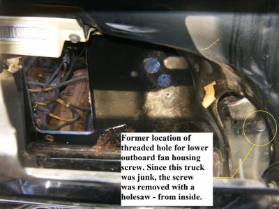
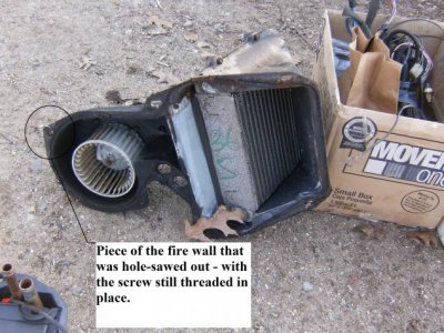
Here is a trick to release the hardest screw to reach - the lower outboard one that holds the blower housing. It is the same on both non-A/C and A/C setups. Remove the blower from the housing and reach down into the vestibule. Move your fingers out toward the fender and you will feel the pointy end (and about 3/4" of the threads) of that screw where they have penetrated the firewall.

Using a small pair of Channelocks, grip the threads and turn the bollt CW (as if tightening). You won't be able to see it, but the head of the screw will start backing off from the blower housing flange. Keep taking little half-turns with the pliers as long as you have something to grip.

You won't be able to turn the screw all the way out from inside the vestibule with your hand down inside - you'll eventually run out of threads to grab. But at some point you can pull the fan housing far enough away from the firewall to allow access to the screw between the housing and firewall. Finish turning it out with a pair of needle nose pliers.

It goes slow due to the lack of room to work in. You only get maybe a 1/4 of a turn each time you re-grip the threads and throw the wrench/pliers - then the handle hits the wall and you have to go back and get a new grip.

Another way you can try is to remove the kickplate and fresh air inlet damper. The end of that bolt will be visible where it penetrates the firewall. It is easy to see and easy to reach into the vestibule but the fact that it is pointing straight at you makes it difficult to turn.
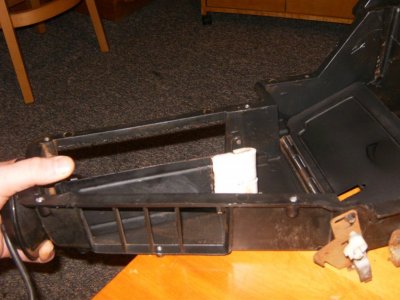
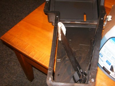
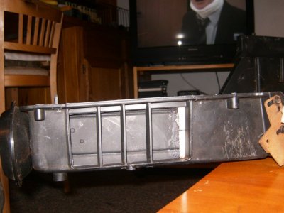

Some visual aids:
 

Attachments

  • HPIM1540.jpg
    HPIM1540.jpg
    93 KB · Views: 250
  • HPIM1544.jpg
    HPIM1544.jpg
    98.2 KB · Views: 263
  • HPIM1551.jpg
    HPIM1551.jpg
    99.7 KB · Views: 269

chengny

Full Access Member
Joined
Feb 22, 2012
Posts
4,086
Reaction score
1,008
Location
NH
First Name
Jerry
Truck Year
1986
Truck Model
K3500
Engine Size
350/5.7
Good detail of the LH (system controlled) outside air inlet damper and actuating components:

You must be registered for see images attach
 

89Suburban

Supporting Member
Supporting Member
Joined
Dec 7, 2010
Posts
24,541
Reaction score
5,846
Location
Southeast PA
First Name
Paw Paw
Truck Year
2007
Truck Model
Chevrolet Tahoe LT
Engine Size
5.3, 4WD
:popcorn:
 

chengny

Full Access Member
Joined
Feb 22, 2012
Posts
4,086
Reaction score
1,008
Location
NH
First Name
Jerry
Truck Year
1986
Truck Model
K3500
Engine Size
350/5.7
Exerpted from two earlier posts in this thread;

Question: I've about fuggin had it with the air distributor box. I've still not got it apart. How the fugg do I get the long shaft out of it so I can seperate the 2 pcs?

Reply: That long shaft is pressed in. Just take pliers and work on the end of it at the bottom to pry it up. It's keyed like slotted shape. One you get it popped out of the lower hinge it should slide right out of the top.

While doing a non-AC to A/C conversion recently it was necessary to make some internal repairs to the air-handling side of the system. When it came time to seperate the 2 halves of the casing, the shaft that is referred to in the question couldn't be extracted by pulling on the upper end.


I encountered the same resistance to removing the operating shaft (item 160) from the "valve" (item 163) as in the question above. Refer to parts dwg attached to post #83.

A few raps with a small ball pein hammer did eventually pop the shaft out of the lower pinion in the valve. No real problem so far, I set the parts aside and continued on with the restoration.

Comes time to reassemble. Trouble began when the valve shaft was inserted through the outer shell and down into the lower pintle of the valve. To test operation and alignment, the driven end of the shaft was twisted and the valve was observed for motion - there was none.


Long story short: the original assembly of the shaft to the valve was made up with some type of epoxy. Found that the lower end of the shaft has a flat side machined (2 steps for some reason). And after disassembling the entire air handler, a close inspection of the ID of the lower pintle was conducted. I could see the remanents of whatever kind of "Miracle Whip" was used. There was still a bit of the flat side formed by the epoxy visible on the inside of the pintle.

But, between removing the shaft with a hammer and cleaning it up with a Scotch-brite pad, there was not enough left for the flat surface on the OD of the shaft to drive the valve.

NOTE: The flat spot is machined so that upon final assembly it is parallel to the leading edge of the valve. See attached images.

It was decided to drill and tap the lower pintle to accept a #10-32 set screw. This was used primarily for alignment during assembly and left slightly loose. Another flat spot was filed into the shaft in the area of the upper pintle to help share the load.

The entire air handler was reassembled - except for the valve operating shaft. Before inserting the shaft a shot of Bondo 2-part epoxy was pressed into the ID's of both the upper and lower pintles.

Once inserted and adjusted to the proper height, the set screw was brought up tight and the epoxy was allowed to set up.

This is not the most well written procedure, but maybe the attached images will help clear things up. They are in no particular order, contain no text and the quality sucks - sorry:
You must be registered for see images attach

You must be registered for see images attach

You must be registered for see images attach

You must be registered for see images attach

You must be registered for see images attach


You must be registered for see images attach
 

austinado16

Full Access Member
Joined
May 25, 2012
Posts
611
Reaction score
221
Location
Central Coast, CA
First Name
Todd
Truck Year
1990 w/307k miles on the clock
Truck Model
GMC V1500 Suburban SLE
Engine Size
5.7L TBI/4L60/3.42's
Thought I'd post a little write up on an issue I've been having for about a year now.

About 18mos ago we were on a long trip to and from Sacramento, towing the popup camper in the heat. Basically 5hrs each way, in 90+ temps, with the front and rear a/c running.

Wound up with melted wiring connectors at the front blower fan, and discovered that the ground wire for the blower was too small, and poorly connected.

Upgraded the ground for the blower with some 2 gage battery ground cable with an eyelet at each end. Upgraded the power wire from the blower relay on the side of the evaporator housing down to the blower with some 8ga.

Thought that would take care of it, but I guess the failure got the rotary control in the HVAC control unit so hot that it melted the rotary control guts.

What I wound up with was a slide control that would barely shut the compressor off in the "off" position, and held the compressor on in the "vent" position.

On top of that, at random, there'd be a melting electrical smell, and recently, even smoke coming out of the center vent area.

Finally got off my lazy a$$ and tore into the problem yesterday:

-Remove instrument panel surround.
-Remove the 4 hex-head screws that hold the HVAC controller to the dash.
-Pull controller out far enough to rotate bulb holder 1/4 turn and pull out the back.
-Pull controller further out of the dash to gain access to the 2 screws that mount the rotary control to the main HVAC control assembly.
-Lift the rotary control straight up and off the main assembly.

Take apart the rotary control:
-Use a wide blad screwdriver to carefully pry the plastic "rivet/plug" out of the center of the rotary assembly. Just place the screwdriver under the round head of the rivet and pry, it'll let go and pop out.
-Lift off the rotary control housing cover:
You must be registered for see images attach


Note the position of the 3 springs, and how they are clocked so you can put it back together in this position. This is the "off" position, and it's how you removed it, and how it'll go back into the main HVAC control assembly.

-Take the springs and the rotary contact plate off.
You must be registered for see images attach


See where my plate was burned and where it was burning the plastic housing?
You must be registered for see images attach


You must be registered for see images attach


I ordered a good used HVAC controller on ebay for $20, but figured I would make an attempt at repairing this one. I cleaned all the grease up and dug the loose stuff out of the holes that had been melted into the plastic. Then I packed the holes with Epoxy Steel Putty:
You must be registered for see images attach


Once cured, I sanded the putty repair areas flat, and trimmed the edges so they lined up with the actual edge of the brass contacts so that the off and on functions would be in the correct locations on the sliding lever.

With this repair complete, the HVAC controls were back functioning corrrectly again. However, there was still a question of why was it getting so hot. I took a look at my battery cable ground wire install and discovered that it was not very tight on the motor housing. I replaced the original screw with a much larger version and used a toothed washer for better grip.

So far, so good.
 

chengny

Full Access Member
Joined
Feb 22, 2012
Posts
4,086
Reaction score
1,008
Location
NH
First Name
Jerry
Truck Year
1986
Truck Model
K3500
Engine Size
350/5.7
Some days you eat the bear; some days the bear eats you

Using the through-bolts in correctly located holes, the flange on the inner half of the air handler was painted with nickel Never-seize. It was then pressed up against the firewall from the inside. This made a nice neat outline of where the new hole should be cut.

After it was used for marking the hole, the air handler was placed on top of the cab (about 7 feet high - the truck is up on stands) to keep it safe from getting stepped on, knocked over on to the floor, etc.

The corners of the marked penetration were detailed with a step drill. Finally slits were cut with a grinder in each plane to allow the insertion of a sawwzall blade in preperation for the final cuts in the firewall.

Then came the sawzalling. The firewall is fairly flexible and so there was quite a bit of vibration - tools and parts were dropping left and right.


When it was all over, I stepped back to admire my work and saw this:


You must be registered for see images attach


There went 3-4 nights work rebuilding that black box - and my wife said that if I went to mass with her my luck would get better.

On the plus side I did find a kid that had one for sale - $25.
 
Last edited:

89Suburban

Supporting Member
Supporting Member
Joined
Dec 7, 2010
Posts
24,541
Reaction score
5,846
Location
Southeast PA
First Name
Paw Paw
Truck Year
2007
Truck Model
Chevrolet Tahoe LT
Engine Size
5.3, 4WD
Using the through-bolts in correctly located holes, the flange on the inner half of the air handler was painted with nickel Never-seize. It was then pressed up against the firewall from the inside. This made a nice neat outline of where the new hole should be cut.

After it was used for marking the hole, the air handler was placed on top of the cab (about 7 feet high - the truck is up on stands) to keep it safe from getting stepped on, knocked over on to the floor, etc.

The corners of the marked penetration were detailed with a step drill. Finally slits were cut with a grinder in each plane to allow the insertion of a sawwzall blade in preperation for the final cuts in the firewall.

Then came the sawzalling. The firewall is fairly flexible and so there was quite a bit of vibration - tools and parts were dropping left and right.


When it was all over, I stepped back to admire my work and saw this:


You must be registered for see images attach


There went 3-4 nights work rebuilding that black box - and my wife said that if I went to mass with her my luck would get better.

On the plus side I did find a kid that had one for sale - $25.

Ahhh noooooo!!!!! :console:
 

chengny

Full Access Member
Joined
Feb 22, 2012
Posts
4,086
Reaction score
1,008
Location
NH
First Name
Jerry
Truck Year
1986
Truck Model
K3500
Engine Size
350/5.7
All rebuilt with the new $25 box. Came out like factory.

Anyway this time when I disassembled it, I took a little more time and paid attention to the defrost damper linkage (as it is assembled to the operating arm).

My images didn't capture which hole in the arm accepts the shaft on the damper crank. And, for whatever reason, 89Suburban's images show it going into both holes in different shots:

You must be registered for see images attach


This is how it comes assembled from the factory:

You must be registered for see images attach


With the pin in the outer hole, the damper strokes fully top to bottom and the gaskets contact the casing as shown:

You must be registered for see images attach
 

89Suburban

Supporting Member
Supporting Member
Joined
Dec 7, 2010
Posts
24,541
Reaction score
5,846
Location
Southeast PA
First Name
Paw Paw
Truck Year
2007
Truck Model
Chevrolet Tahoe LT
Engine Size
5.3, 4WD
All rebuilt with the new $25 box. Came out like factory.

Anyway this time when I disassembled it, I took a little more time and paid attention to the defrost damper linkage (as it is assembled to the operating arm).

My images didn't capture which hole in the arm accepts the shaft on the damper crank. And, for whatever reason, 89Suburban's images show it going into both holes in different shots:

You must be registered for see images attach


This is how it comes assembled from the factory:

You must be registered for see images attach


With the pin in the outer hole, the damper strokes fully top to bottom and the gaskets contact the casing as shown:

You must be registered for see images attach

Yah it was in the one hole and I changed it to the other one to get the full stroke of it to shut the floor off and give full blast to the defrost. Made a huge difference. Plus the gasket on mine was gone too. :(

I don't know if the PO had put it together wrong or not, it was apart before.
 

chengny

Full Access Member
Joined
Feb 22, 2012
Posts
4,086
Reaction score
1,008
Location
NH
First Name
Jerry
Truck Year
1986
Truck Model
K3500
Engine Size
350/5.7
At least you had the presence of mind to record the position before disassembling the thing. I rushed, as usual. So, when it came time to put everything back together this is what I had for reference:
 

Attachments

  • HPIM1583.jpg
    HPIM1583.jpg
    93.6 KB · Views: 276
  • HPIM1584.jpg
    HPIM1584.jpg
    91.8 KB · Views: 276

89Suburban

Supporting Member
Supporting Member
Joined
Dec 7, 2010
Posts
24,541
Reaction score
5,846
Location
Southeast PA
First Name
Paw Paw
Truck Year
2007
Truck Model
Chevrolet Tahoe LT
Engine Size
5.3, 4WD
I see the gasket on yours is missing as well, are you doing anything with that or leaving it like it is. I see it in the one diagram you posted on part #166, there is a good detailed pic of the gasket part.

You must be registered for see images
 

chengny

Full Access Member
Joined
Feb 22, 2012
Posts
4,086
Reaction score
1,008
Location
NH
First Name
Jerry
Truck Year
1986
Truck Model
K3500
Engine Size
350/5.7
I tried to duplicate the original design of the gasket on the tip of the defrost divert damper.

The damper was masked off - except for the gasketed area. The end was then sprayed with 3M Super 77 and allowed to become tacky. Two strips of weather stripping (1" Wide X 3/8" Thick) were applied.

To get the weather stripping to conform to the stepped contour of the damper required several stages of clamping in the vise. It came out like this (after the compression marks from the vise were allowed to relax, they actually looked much better) :
 

Attachments

  • HPjIM1624 (8).jpg
    HPjIM1624 (8).jpg
    94.6 KB · Views: 337
  • HPjIM1624 (3).jpg
    HPjIM1624 (3).jpg
    94.2 KB · Views: 324
  • HPjIM1624 (7).jpg
    HPjIM1624 (7).jpg
    93.1 KB · Views: 318
Last edited:

89Suburban

Supporting Member
Supporting Member
Joined
Dec 7, 2010
Posts
24,541
Reaction score
5,846
Location
Southeast PA
First Name
Paw Paw
Truck Year
2007
Truck Model
Chevrolet Tahoe LT
Engine Size
5.3, 4WD
0.o
 

chengny

Full Access Member
Joined
Feb 22, 2012
Posts
4,086
Reaction score
1,008
Location
NH
First Name
Jerry
Truck Year
1986
Truck Model
K3500
Engine Size
350/5.7
Yeah, I know. Not my best work- it looks like crap. But it seems to form a good seal at the top and bottom.

And, the stuff really sticks on. I did it twice - the first attempt was pathetic.

When I went to remove it; took me forever. I had to tear it off, wire brush the remanants, and scrub/dissolve with acetone to get back to metal.
 

89Suburban

Supporting Member
Supporting Member
Joined
Dec 7, 2010
Posts
24,541
Reaction score
5,846
Location
Southeast PA
First Name
Paw Paw
Truck Year
2007
Truck Model
Chevrolet Tahoe LT
Engine Size
5.3, 4WD
I'm just playing with ya, you did good. :)

Just don't drop the damn thing again lol.
 

Latest posts

Forum statistics

Threads
42,203
Posts
911,272
Members
33,697
Latest member
jingle1
Top