Well I stirred up a hornets nest on the Edelbrock forum with questioning the placement of the O2 sensor. Finally a tech moderator chimed in. Posting for general FYI on the subject:
"A Bosch LSU 4.9 Oxygen Sensor does not measure Oxygen.
It measures the Current going in and out of a Nernst Cell.....
https://en.wikipedia.org/wiki/Nernst_equation
One side of the Cell is pumping ION's in. Other side is pushing the ION's into the middle of the Cell.....after some Calibration, and using a algorithm associated with the fuel type used, a air to "other stuff" can be calculated.
In order for the ION's to move freely within the Nernst Cell it must be heated to around 800F. To cold and they don't move. To hot and the Cell is destroyed....... upstream, and downstream O2 sensors are specifically designed for the "Temperature Range" they are going to in counter......O2 sensors that come with the Edelbrock kits are upstream units.
__________________________________________________ _____________________________
The Throttle Body, and Intake Manifolds used in Edelbrock's kit are engineered to "uniformly" and "consistently" fill all cylinders the same.
__________________________________________________ _____________________________
Cylinder Heads are the magical ONE WAY FLOW DEVICES that enable humans to make vehicles faster then other types of animals.
The Atomized Fuel ( from a injector or carburetor ) will get vaporized ( turned into a gas ) when it's in contact with the "heated" Intake Valve.
Do to the fact we don't have Air Heaters, or Glow Plugs. It takes some time for the Intake Valve to "consistently" vaporize the atomized fuel.
Hence why all EFI systems will rev a motor past it's normal idle speed when first started cold....builds up cylinder heat faster.
Do to the fact each cylinder warms up a tiny bit different then the others ( Ford had a "fix" for some of it's European vehicles..Google Ford coolant system fires ) you will always have a very small difference of fuel requirements for each cylinder when cold.
But, once the motor is warm. All cylinders should be symmetrical in their fuel requirements...... mechanical issues do change this. Bad valve seals, worn rings, etc.
__________________________________________________ _____________________________
Edelbrock's Calibration maps are Dyno tested using stock and their own aftermarket parts.
Or put another way: If the stock motor had major issues with fuel distribution that could not be improved with Edelbrock's intake manifold. Then a kit would not be produced for that motor....Buick, and Ford Flatheads.
__________________________________________________ ______________________________
Exhaust Manifolds, and Headers.
Manifolds are designed thick to reduce the motors noise level.
Headers are made thin do to the pipes needing to be bent during the construction of the headers.
No Automobile Manufacturer uses Long Tube Headers with the Above Bosch O2 sensor......Google-images Ferrari F40 exhaust manifold, to see a true high performance header....see how it starts thick to keep the heat in the assembly. 100% opposite of traditional long headers.
A vehicle manufacturer is not going to "rely" on the O2's heater for consistent operation.....ever seen a O2 on the exhaust systems tip?
Their going to place the sensor in a section of the exhaust that consistently stays around 800F.
Most O2's are installed about two feet from the exhaust valve..... catalytic converter O2's are inches from them....the heat source.
__________________________________________________ _______________________________
Conclusion:
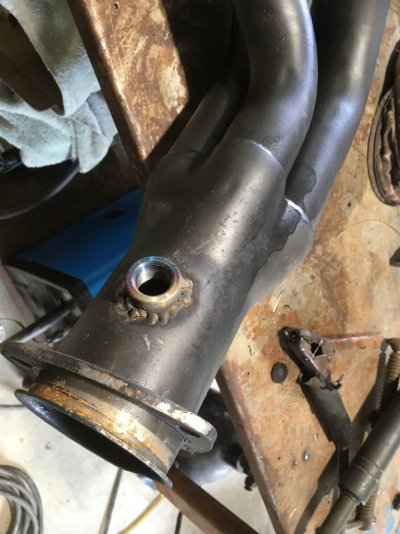
Installation of the O2 should be close to the exhaust valve.
It's distance is dictated by "actually" testing it's location.....Hint: Welders use a paint crayon that melts at a set temperature.
Cylinder imbalance generally only occurs during cold starts, and it's only temporary for a very short time.
Hence: Over think the O2 Installation. Don't over think cylinder imbalance.