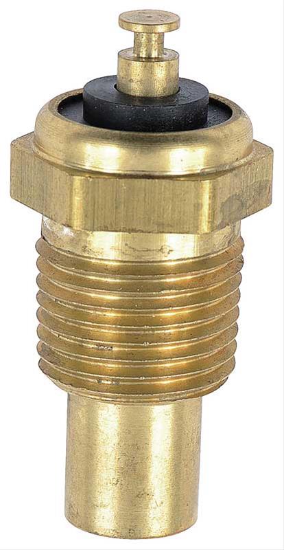
The temp gauge circuit is very simple.
- 12 volts applied to one gauge terminal when ignition is on
- other gauge terminal connects through cluster wiring to the green sending unit wire in the engine compartment, which is clipped on to the sending unit terminal
- sending unit is a resistor that varies resistance based on temperature of the engine
- low temp/ high resistance in sending unit - gauge needle moves a little, but reads low
- high temp/ low resistance in sending unit - gauge needle moves higher
- sending unit body/threads must be grounded to the engine to complete the circuit, so do not wrap threads with sealer tape
For testing
- if the sending unit wire is grounded (zero resistance), gauge needle goes to max
- you can use small resistors (like from the old Radio Shack), connected between the sending unit wire and an engine ground, to simulate the 0-max ohm resistance and see what the gauge reads. Max resistance is quite high (maybe as high as 3000-4000 ohms, or more) not the 90 ohms max for a fuel sending unit.
The resistance “profile” (what resistance matches each gauge reading) of the sending units has changed over the years of the squarebody, and some of the early Delco sending units have been discontinued. The connector on the end of the sending unit has also changed ( button vs. pin, etc.). It may take some time to find a sending unit that is the correct match to your gauge.
I found only a fairly close match to my ‘75 SBC sending unit, since the original Delco part has been discontinued.