Hooking Up Heat/AC during rewire...

Disclaimer: Links on this page pointing to Amazon, eBay and other sites may include affiliate code. If you click them and make a purchase, we may earn a small commission.

R8rPhan

Full Access Member
Joined
Feb 5, 2017
Posts
452
Reaction score
42
Location
California
First Name
Mark
Truck Year
1973 (1979?)
Truck Model
C10 long bed (Frankenstein truck)
Engine Size
307
I have a cab on my truck that appears to be a 79.. I pulled all the wiring harnesses out, except for those having to do with the Heater/AC...

I am using an EZ Wire kit for the rewire, have it mostly all done/figured out except for a couple things.. One of them is the Heat/AC system

The kit gives me two wires to hook up to the Heat/AC... One is labeled "Heat/AC power" and this I'm "Pretty sure" is supposed to be the power that goes to the fan switch in the cab...

The other is labeled "AC Compressor" and this is the one I'm not really sure about...

The existing wiring has a red wire (looks to be about #10 gauge), that went from the junction block fusible link on the fire wall to the AC system.. Pretty sure this wire goes to the relay near the accumulator.. There are three other wires that go into a connector harnessed with that red wire, that I am assuming went to the compressor? I don't know for sure because there is no compressor in the truck at this time, but I don't remember anything being hooked to this connector.. So that is my semi-uneducated guesstimification...

The wire in the new harness is probably a #16 and I am guessing that both wires in the new harness ("Heat/AC power" and "AC Compressor") go directly to the fuse box, both being supplied by a 30A fuse...

Now because of all of that, I'm guessing that the one labeled "AC Compressor" is supposed to be spliced to the large RED wire going to the fan relay next to the evaporator, but the size difference gives me pause...

Can anyone shed any light on this?

Here are some pictures of the wires involved...


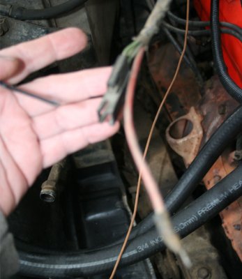
This is the existing red wire and connector that go to the Heat AC system

attachment.php


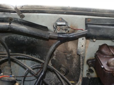
This is the junction block that the red wire was previously connected to..

attachment.php


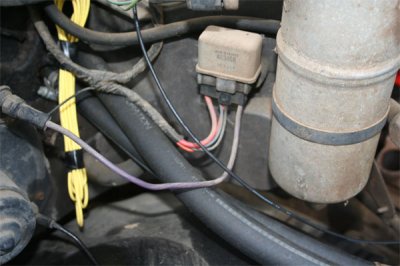
And this is the Relay that I believe the Red wire is currently connected to

attachment.php


Am I correct in thinking that I am supposed to connect the black "AC Compressor" wire from the new harness to the existing red wire that goes to the AC system? Is the size difference an issue?

How much current would that red wire normally be expected to carry if I had the compressor in the truck and hooked up? (I do plan on doing just that at some point)

Thanks,
Mark
:cheers:
 

Attachments

  • 73-C10-Heat-AC-wiring-1.jpg
    73-C10-Heat-AC-wiring-1.jpg
    67.3 KB · Views: 2,256
  • 73-C10-Heat-AC-wiring-2.jpg
    73-C10-Heat-AC-wiring-2.jpg
    55.1 KB · Views: 3,480
  • Junction-Block-3.jpg
    Junction-Block-3.jpg
    61.1 KB · Views: 2,658

75gmck25

Full Access Member
Joined
Oct 13, 2016
Posts
2,060
Reaction score
1,865
Location
Northern Virginia
First Name
Bruce
Truck Year
1975
Truck Model
K25 Camper Special TH350 NP203
Engine Size
5.7
I'll explain how my '75 truck is wired, but yours may not be identical.

Blower speeds
The 10 gauge red wire runs from the junction block near the brake booster, over to a 30 amp inline fuse holder, and then over to the high speed blower relay.
The first two blower speeds (there is no off position) run through the resistor pack and get power from the switch in the controls. However, when you switch it to the highest speed it activates the high blower speed relay on the plenum under the hood, and the blower gets power directly through the 30 amp fuse connection.

Compressor
The compressor is grounded to the engine through the mounting brackets.
The compressor power wire runs from the A/C switch in the controls, and the power is is cycled on/off through the thermostatic switch that is inserted in the evaporator core (switch has a long nail-like probe that sticks through the evaporator fins). The thermostatic switch will apply power to the compressor until temp at the evaporator gets down to about 35-40 degrees, and then cycle the compressor off. In addition, the compressor power wire runs through the low-pressure switch (protects against low charge) in the AC line near the plenum, along the back of the engine, and then along the driver's side valve cover to the compressor.

The low pressure switch has a large plug (bigger than a quarter), that you pull off to see the two terminals inside. With the plug removed you can put a jumper between the two slots in the plug so that the compressor will come on even if there is low pressure. You may need to use that jumper to make the compressor activate when you manually charge the system with a small can of refrigerant.

Bruce
 

R8rPhan

Full Access Member
Joined
Feb 5, 2017
Posts
452
Reaction score
42
Location
California
First Name
Mark
Truck Year
1973 (1979?)
Truck Model
C10 long bed (Frankenstein truck)
Engine Size
307
I'll explain how my '75 truck is wired, but yours may not be identical.

Blower speeds
The 10 gauge red wire runs from the junction block near the brake booster, over to a 30 amp inline fuse holder, and then over to the high speed blower relay.
The first two blower speeds (there is no off position) run through the resistor pack and get power from the switch in the controls. However, when you switch it to the highest speed it activates the high blower speed relay on the plenum under the hood, and the blower gets power directly through the 30 amp fuse connection.

Compressor
The compressor is grounded to the engine through the mounting brackets.
The compressor power wire runs from the A/C switch in the controls, and the power is is cycled on/off through the thermostatic switch that is inserted in the evaporator core (switch has a long nail-like probe that sticks through the evaporator fins). The thermostatic switch will apply power to the compressor until temp at the evaporator gets down to about 35-40 degrees, and then cycle the compressor off. In addition, the compressor power wire runs through the low-pressure switch (protects against low charge) in the AC line near the plenum, along the back of the engine, and then along the driver's side valve cover to the compressor.

The low pressure switch has a large plug (bigger than a quarter), that you pull off to see the two terminals inside. With the plug removed you can put a jumper between the two slots in the plug so that the compressor will come on even if there is low pressure. You may need to use that jumper to make the compressor activate when you manually charge the system with a small can of refrigerant.

Bruce

Okay, so that explains why there are two wires from the same fuse, one on one side of the firewall, and one on the other... One powers the switch (for the low speeds) and one powers the relay for the high speed...

Do you have any idea how much current is drawn through power supply (The big red wire) on the high speed side when the fan and compressor are drawing from it?

I am concerned about why the wire in the kit is so much smaller than the red one, and both are fed off of a 30A fuse.... Because a #16 probably shouldn't be asked to carry more than 10A or so...

So basically, I guess what I need to know is how much current the fan draws max, and how much current the compressor draws max.. The power to the compressor is just to power the clutch I think....

I'm pretty sure that the way it was wired before, is that the wire from the starter battery post went to that junction block on the firewall (with the fusible link in it), and then the power for the system came off of the other side and that is where the red wire was attached also...

I might take the red wire from the AC and re land it on the junction block and then tie the new compressor power wire to the other terminal.. That way, if it ever proves to be an issue, I can always run a new wire directly from the battery and replace the AC power wire from the kit with it, or even intercept the wire coming off the batt terminal on the batter and run it through the junction block like it originally was?
:shrug:

Thanks,
Mark
:cheers:
 
Last edited:

75gmck25

Full Access Member
Joined
Oct 13, 2016
Posts
2,060
Reaction score
1,865
Location
Northern Virginia
First Name
Bruce
Truck Year
1975
Truck Model
K25 Camper Special TH350 NP203
Engine Size
5.7
The high speed blower power wire appears to be 10 gauge, and it was connected from the blower relay, through a 30 amp fuse holder, to the junction on the firewall .

My blower on high speed drew so much power that it melted the old fuse holder (probably corroded inside), so I replaced it with a newer 30 amp holder with a 30 amp blade fuse. Haven't had trouble since.

1975 wiring ( before power windows & locks)
The 10 gauge power wire from the starter post runs up to that same firewall junction, and there is a 14 gauge fusible link (I think there is a FL on both ends).

I don't know the current draw for the compressor, but it does not look like a very large wire - maybe 16 or 14 gauge?

Bruce
 

gmachinz

Harnessworx Inc
Joined
Nov 10, 2012
Posts
762
Reaction score
288
Location
Iowa
First Name
Jabin
Truck Year
1986
Truck Model
K10
Engine Size
350
All speeds but high speed have to go through the resistor coils so the amperage is fairly low, the AC/Heat fuse panel lead should go to your climate control input brown w/white stripe. From there, the switch routes power through the resistor could, and the AC compressor runs through the low pressure switch on the drier and you may/may not have an ambient temp switch too-do you have any manuals covering the trucks wiring schematics?
 

gmachinz

Harnessworx Inc
Joined
Nov 10, 2012
Posts
762
Reaction score
288
Location
Iowa
First Name
Jabin
Truck Year
1986
Truck Model
K10
Engine Size
350
And, being a 79 chassis, your main AC power may be yellow instead of brown w/wht-the colors changed in 1981. That firewall connector with 2 greens is:

Dark green AC compressor feed
Light green AC pressure switch feed to idle stop solenoid.
 

R8rPhan

Full Access Member
Joined
Feb 5, 2017
Posts
452
Reaction score
42
Location
California
First Name
Mark
Truck Year
1973 (1979?)
Truck Model
C10 long bed (Frankenstein truck)
Engine Size
307
All speeds but high speed have to go through the resistor coils so the amperage is fairly low, the AC/Heat fuse panel lead should go to your climate control input brown w/white stripe. From there, the switch routes power through the resistor could, and the AC compressor runs through the low pressure switch on the drier and you may/may not have an ambient temp switch too-do you have any manuals covering the trucks wiring schematics?


All of the original AC/Heat wiring harness is still in the truck, seeing as that was a separate harness, and the kit didn't come with one, I left it alone..

I'm mainly just trying to supply power to it from the two leads the kit does include..

I'm kinda concerned about the wire size difference between the wire being fed and the wire from the kit supplying it (on the engine side of the firewall)..

Need to figure out how much current the AC draws through that wire (fan at max, AC Compressor engaged), so that I can feel at ease about the #16 wire that feeds it...

If it's under 10-12 amps, it should be fine... Over that, and it starts getting kinda iffy..
 

R8rPhan

Full Access Member
Joined
Feb 5, 2017
Posts
452
Reaction score
42
Location
California
First Name
Mark
Truck Year
1973 (1979?)
Truck Model
C10 long bed (Frankenstein truck)
Engine Size
307
I don't know the current draw for the compressor, but it does not look like a very large wire - maybe 16 or 14 gauge?

Bruce

That's a good point..

Was searching the web some last night, and I saw others talking about how the compressor clutch (which is evidently what the power to the compressor itself is for) draws about three and a half amps, which would not be an issue for the wire the kit supplies... I think this was for a similar year trans am or a vette (forgot which forum I saw that in, could've been a truck forum even).. But the compressors are likely similar if not the same...

So, now I need to know what the draw is for the fan at high speed...
 

gmachinz

Harnessworx Inc
Joined
Nov 10, 2012
Posts
762
Reaction score
288
Location
Iowa
First Name
Jabin
Truck Year
1986
Truck Model
K10
Engine Size
350
All of the original AC/Heat wiring harness is still in the truck, seeing as that was a separate harness, and the kit didn't come with one, I left it alone..

I'm mainly just trying to supply power to it from the two leads the kit does include..

I'm kinda concerned about the wire size difference between the wire being fed and the wire from the kit supplying it (on the engine side of the firewall)..

Need to figure out how much current the AC draws through that wire (fan at max, AC Compressor engaged), so that I can feel at ease about the #16 wire that feeds it...

If it's under 10-12 amps, it should be fine... Over that, and it starts getting kinda iffy..
It's not quite as much as amp draw being excessive as being constant-that main feed wire gets hot over time and will melt the AC feed connector-in my AC/climate control harnesses I always upgrade the main feed to 12ga only because I don't have to provide millions of harnesses...lol
 

R8rPhan

Full Access Member
Joined
Feb 5, 2017
Posts
452
Reaction score
42
Location
California
First Name
Mark
Truck Year
1973 (1979?)
Truck Model
C10 long bed (Frankenstein truck)
Engine Size
307
It's not quite as much as amp draw being excessive as being constant-that main feed wire gets hot over time and will melt the AC feed connector-in my AC/climate control harnesses I always upgrade the main feed to 12ga only because I don't have to provide millions of harnesses...lol

The current draw of that fan is gonna tell the story... Can't seem to find the info though...


I'm gonna go ahead and land it through the existing junction block/fusible link.. It's gonna be a while before I work on getting the AC going, will need a compressor, bracket and hoses at the least before I do... So, if at that time, I decide I want a heavier wire, I can either run the #10 off the batt terminal of the starter through the junction block too, or feed it directly off the battery itself, which might be the best way, as then I can also send the alt output to the same place if I decide I ever want a bigger than 80A alternator (which seeing as I plan to put a power takeoff for a semi-portable winch on the truck at some point could definitely happen)..


Is the 'max fan speed' only when the AC is being used? Or is it available for heat/defrost only as well?
 

gmachinz

Harnessworx Inc
Joined
Nov 10, 2012
Posts
762
Reaction score
288
Location
Iowa
First Name
Jabin
Truck Year
1986
Truck Model
K10
Engine Size
350
The current draw of that fan is gonna tell the story... Can't seem to find the info though...


I'm gonna go ahead and land it through the existing junction block/fusible link.. It's gonna be a while before I work on getting the AC going, will need a compressor, bracket and hoses at the least before I do... So, if at that time, I decide I want a heavier wire, I can either run the #10 off the batt terminal of the starter through the junction block too, or feed it directly off the battery itself, which might be the best way, as then I can also send the alt output to the same place if I decide I ever want a bigger than 80A alternator (which seeing as I plan to put a power takeoff for a semi-portable winch on the truck at some point could definitely happen)..


Is the 'max fan speed' only when the AC is being used? Or is it available for heat/defrost only as well?
Max fan speed can be AC, heat, defrost-it just runs the fan at nearly full speed. There are many areas of the factory wiring that should be updated unfortunately nobody who offers "universal" circuit harnesses knows anything other than the way GM did it-that's the difference between companies offering harnesses based off outdated prints and those who offer update versions with modern upgrades factored in-but if you're willing to figure it out, you can save a little $$ possibly.
 

R8rPhan

Full Access Member
Joined
Feb 5, 2017
Posts
452
Reaction score
42
Location
California
First Name
Mark
Truck Year
1973 (1979?)
Truck Model
C10 long bed (Frankenstein truck)
Engine Size
307
Max fan speed can be AC, heat, defrost-it just runs the fan at nearly full speed. There are many areas of the factory wiring that should be updated unfortunately nobody who offers "universal" circuit harnesses knows anything other than the way GM did it-that's the difference between companies offering harnesses based off outdated prints and those who offer update versions with modern upgrades factored in-but if you're willing to figure it out, you can save a little $$ possibly.


Okay, landed some of this stuff.. But things are not what I thought...

The wire labeled "AC Compressor Power" is actually #14, so it can handle 15-18 amps... HOWEVER, it does not appear to be coming from the fuse panel as I thought, but rather is just routed back into the cab area (presumably to the Heat/AC control UI)..

So in order to get full power to the Fan/AC Blower and power to the compressor, I guess I need to cut the wire coming from the Batt terminal of the starter to the fuse block (main power) and put that fusible link/Junction block that is on the firewall in series with it...

and 'that' should give power to the AC Blower relay, while the 'other' wire in the cab, labeled "Heat/AC power" is to be connected to the brown wire on the fan switch harness..

That's the best I can figure out, and I have no idea what the intended purpose of the "AC Compressor power" wire is..

Will probably just tape of the ends and leave it alone...

So, I am thinking, that once I put power to that junction block via the main power feed from the battery/Starter, and then splice the "Heat/AC power" wire from the fuse block to the brown wire of fan switch.. it should all work?


All of the factory wiring AC/Heat harness is still intact.. So I'm thinking it 'should' work...

Maybe when I'm ready to get the AC working, I'll have you make me a new updated harness for that?
 

gmachinz

Harnessworx Inc
Joined
Nov 10, 2012
Posts
762
Reaction score
288
Location
Iowa
First Name
Jabin
Truck Year
1986
Truck Model
K10
Engine Size
350
Okay, landed some of this stuff.. But things are not what I thought...

The wire labeled "AC Compressor Power" is actually #14, so it can handle 15-18 amps... HOWEVER, it does not appear to be coming from the fuse panel as I thought, but rather is just routed back into the cab area (presumably to the Heat/AC control UI)..

So in order to get full power to the Fan/AC Blower and power to the compressor, I guess I need to cut the wire coming from the Batt terminal of the starter to the fuse block (main power) and put that fusible link/Junction block that is on the firewall in series with it...

and 'that' should give power to the AC Blower relay, while the 'other' wire in the cab, labeled "Heat/AC power" is to be connected to the brown wire on the fan switch harness..

That's the best I can figure out, and I have no idea what the intended purpose of the "AC Compressor power" wire is..

Will probably just tape of the ends and leave it alone...

So, I am thinking, that once I put power to that junction block via the main power feed from the battery/Starter, and then splice the "Heat/AC power" wire from the fuse block to the brown wire of fan switch.. it should all work?


All of the factory wiring AC/Heat harness is still intact.. So I'm thinking it 'should' work...

Maybe when I'm ready to get the AC working, I'll have you make me a new updated harness for that?
If you need a complete NEW AC climate control harness I've got them in stock. I like to add a relay to handle the load of running the compressor too-it really helps maintain voltage when the compressor is engaged. Again, the climate control main power feed runs the compressor as well as the blower motor...now you can start to see why I prefer running a 12ga supply feed from the fuse panel to the AC head unit.
 

R8rPhan

Full Access Member
Joined
Feb 5, 2017
Posts
452
Reaction score
42
Location
California
First Name
Mark
Truck Year
1973 (1979?)
Truck Model
C10 long bed (Frankenstein truck)
Engine Size
307
If you need a complete NEW AC climate control harness I've got them in stock. I like to add a relay to handle the load of running the compressor too-it really helps maintain voltage when the compressor is engaged. Again, the climate control main power feed runs the compressor as well as the blower motor...now you can start to see why I prefer running a 12ga supply feed from the fuse panel to the AC head unit.

What do you get for those?
 

gmachinz

Harnessworx Inc
Joined
Nov 10, 2012
Posts
762
Reaction score
288
Location
Iowa
First Name
Jabin
Truck Year
1986
Truck Model
K10
Engine Size
350
What do you get for those?

Complete AC climate control harness is $139. This includes a relay upgrade for the AC compressor.
 

Latest posts

Forum statistics

Threads
42,382
Posts
914,888
Members
33,890
Latest member
ehernandez
Top