

You are using an out of date browser. It may not display this or other websites correctly.
You should upgrade or use an alternative browser.
You should upgrade or use an alternative browser.
ac vacuum lines
- Thread starter kc87
- Start date
Disclaimer: Links on this page pointing to Amazon, eBay and other sites may include affiliate code. If you click them and make a purchase, we may earn a small commission.
Norwester
Full Access Member
- Joined
- Jul 3, 2015
- Posts
- 127
- Reaction score
- 9
- Location
- Battle Ground, WA
- First Name
- David
- Truck Year
- 1986
- Truck Model
- C-10
- Engine Size
- 350
So.......'86......a/c......automatic
Looking at the supplied hose diagrams, I'm looking for a tan source line?
I'm not planning on using a/c. Can I eliminate any hoses...and should I?
Looking at the supplied hose diagrams, I'm looking for a tan source line?
I'm not planning on using a/c. Can I eliminate any hoses...and should I?
sealacamp
Junior Member
- Joined
- Jan 28, 2015
- Posts
- 24
- Reaction score
- 3
- Location
- Fairburn GA
- First Name
- Paul
- Truck Year
- 81, 78
- Truck Model
- C10
- Engine Size
- 350
Well I found out what my problem was eventually. The vacuum canister had been removed so that the vacuum line was connected to the wrong port from the carb, via a mechanic I hired who clearly didn't know what he was doing. I put in a new vacuum canister and routed the vacuum line to the intake manifold, problem solved. Good grief sometimes even the simplest things can cause a big headache.
jasonsch
Junior Member
- Joined
- Nov 28, 2015
- Posts
- 3
- Reaction score
- 0
- Location
- South Dakota
- First Name
- Jason
- Truck Year
- 1985
- Truck Model
- C10 Suburban
- Engine Size
- 305
This is my 1st post!! 
Glad I found this site!!
I'm hoping you folks can help me out here...
I have a C10 85 Suburban 2wd with air.
The vacuum is connected correctly to the reservoir on the inner left fender,
and I have vacuum inside.
Every thing works - except for the defrost.
And, like an idiot, I've waited too long to fix it...
It's cold and we had a few inches of snow today - I really need my defroster!!
The above picture shows the actuator/door where the air is directed to the
floor or is closed off - This is working fine.
Is this picture upside-down??
I am thinking it's this actuator that's the problem - but I am not absolutely sure
about that. As said above - this is on the back-side right next to the firewall.
I don't want to tear it all apart to get to this actuator unless I am positive this
is the correct actuator - The one that turns the defroster on.
And - is it possible that the controller (in the dash) could be the problem?
I would think if it all works - except for the defrost mode - the controller would
not be the problem. Then again - I'm just assuming that.
I "meant to" have this fixed before winter set it - but winter is here and now I
need my defroster!!!
Again - I'm glad I found this site!!
And I appreciate any help or advice you may have.
Thank You!!
Glad I found this site!!
I'm hoping you folks can help me out here...
I have a C10 85 Suburban 2wd with air.
The vacuum is connected correctly to the reservoir on the inner left fender,
and I have vacuum inside.
Every thing works - except for the defrost.
And, like an idiot, I've waited too long to fix it...
It's cold and we had a few inches of snow today - I really need my defroster!!
http://www.gmsquarebody.com/forum/attachment.php?attachmentid=5514&d=1335143549Last one is the solid black. It connects to the actuator located on the left side of the unit. Just left of the floor air outlet. This damper switches air from floor to defrost.
The above picture shows the actuator/door where the air is directed to the
floor or is closed off - This is working fine.
http://www.gmsquarebody.com/forum/attachment.php?attachmentid=5512&d=1335141944Next are the brown and blue lines. These run to an actuator located on the back side of the unit and I don't think you can even get to it while its installed in the truck. This actuator operates the damper that switches from vents to floor/defrost. The blue connects to the nipple on the side of the actuator and the brown connects to the nipple in the center of the actuator.
Is this picture upside-down??
I am thinking it's this actuator that's the problem - but I am not absolutely sure
about that. As said above - this is on the back-side right next to the firewall.
I don't want to tear it all apart to get to this actuator unless I am positive this
is the correct actuator - The one that turns the defroster on.
And - is it possible that the controller (in the dash) could be the problem?
I would think if it all works - except for the defrost mode - the controller would
not be the problem. Then again - I'm just assuming that.
I "meant to" have this fixed before winter set it - but winter is here and now I
need my defroster!!!
Again - I'm glad I found this site!!
And I appreciate any help or advice you may have.
Thank You!!
djfour
Junior Member
- Joined
- Jun 23, 2016
- Posts
- 1
- Reaction score
- 0
- Location
- TX
- First Name
- Ryan
- Truck Year
- 1984
- Truck Model
- G2500 Vandura
- Engine Size
- v8
I always wondered about the function of the ridiculous looking bulb attached to the underside of the hood. Just curious, as this spaghetti of hoses that seem to control the position of the airflow between vents/floor/defrost, would leaks of any of these hoses actually prevent the a/c compressor from turning on and delivering "COLD" air?
By the way, this thread is so amazingly informative; big thanks to the OP!
By the way, this thread is so amazingly informative; big thanks to the OP!
yevgenievich
Full Access Member
- Joined
- Mar 1, 2014
- Posts
- 4,829
- Reaction score
- 3,441
- Location
- Place
- First Name
- Name
- Truck Year
- Year
- Truck Model
- Model
- Engine Size
- Size
I always wondered about the function of the ridiculous looking bulb attached to the underside of the hood. Just curious, as this spaghetti of hoses that seem to control the position of the airflow between vents/floor/defrost, would leaks of any of these hoses actually prevent the a/c compressor from turning on and delivering "COLD" air?
By the way, this thread is so amazingly informative; big thanks to the OP!
None of the vacuum hoses will stop the compressor. The heat/cold blend door is controlled by cable. It should blow cold through some of the vents if compressor is running with good pressures
bwilhite1
Member
- Joined
- May 14, 2015
- Posts
- 39
- Reaction score
- 8
- Location
- al
- First Name
- bruce
- Truck Year
- 1986
- Truck Model
- k10
- Engine Size
- 350
Well I found out what my problem was eventually. The vacuum canister had been removed so that the vacuum line was connected to the wrong port from the carb, via a mechanic I hired who clearly didn't know what he was doing. I put in a new vacuum canister and routed the vacuum line to the intake manifold, problem solved. Good grief sometimes even the simplest things can cause a big headache.
The locations of some components may differ slightly - as could the physical appearance - but the fundamentals will apply to your truck.
Do you guys have a picture or location of the vacuum reservoir that controls the AC system? I've got a crate motor in my truck and some of the vacuum components were removed. The heater box does have some vacuum lines running to it from the AC controller in the cab, but that's it as best as I can tell. I do have one vacuum reservoir on the firewall on top of the driver's side fender, but it's not connected to anything.
bwilhite1
Member
- Joined
- May 14, 2015
- Posts
- 39
- Reaction score
- 8
- Location
- al
- First Name
- bruce
- Truck Year
- 1986
- Truck Model
- k10
- Engine Size
- 350
Hey guys I need a little help here. I'm trying to figure out where all the vacuum lines go that run the AC duct dampers. I've found very little info on this and my manual leaves a lot to be desired. Does anyone have a diagram for these lines or know where I can find one? Thanks
OP, you have any advice on previous post?
sealacamp
Junior Member
- Joined
- Jan 28, 2015
- Posts
- 24
- Reaction score
- 3
- Location
- Fairburn GA
- First Name
- Paul
- Truck Year
- 81, 78
- Truck Model
- C10
- Engine Size
- 350
Do you guys have a picture or location of the vacuum reservoir that controls the AC system? I've got a crate motor in my truck and some of the vacuum components were removed. The heater box does have some vacuum lines running to it from the AC controller in the cab, but that's it as best as I can tell. I do have one vacuum reservoir on the firewall on top of the driver's side fender, but it's not connected to anything.
I don't have a photo of mine but it's very simple. There is a vacuum canister that only allows vacuum one way, it's oem and there are plenty of them around, mine is the shape of a ball, most of them are. Mine was on the firewall but that area is not in good shape, need some rework and it's crowed between the fan and the evaporator coil housing anyway. So I relocated my to the inner fender area, plenty of room there and easy to get the lines hooked up. This is just temporary for me though as I will be putting in a vintage air system as soon as I can get around to it. It's a work in progress, and who ever owned that truck before me was not very nice to it, like a lot of vehicles out there, people just don't take care of them.
Good luck, hope that helps a bit.
bwilhite1
Member
- Joined
- May 14, 2015
- Posts
- 39
- Reaction score
- 8
- Location
- al
- First Name
- bruce
- Truck Year
- 1986
- Truck Model
- k10
- Engine Size
- 350
I don't have a photo of mine but it's very simple. There is a vacuum canister that only allows vacuum one way, it's oem and there are plenty of them around, mine is the shape of a ball, most of them are. Mine was on the firewall but that area is not in good shape, need some rework and it's crowed between the fan and the evaporator coil housing anyway. So I relocated my to the inner fender area, plenty of room there and easy to get the lines hooked up. This is just temporary for me though as I will be putting in a vintage air system as soon as I can get around to it. It's a work in progress, and who ever owned that truck before me was not very nice to it, like a lot of vehicles out there, people just don't take care of them.
Good luck, hope that helps a bit.
That's what's on the driver's side of the firewall, but I think it was originally for something else. I was going to run a vacuum line to it, but there is only one place to plug in on it (on top), and it looks like the fitting is broken off. There's nothing on my firewall between the blower motor and evaporator coil.
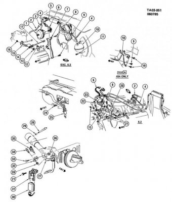
Edit to add: I have part #10 on the attached diagram. My truck doesn't have cruise, so I don't have part #1. I assume parts 2,3 have been removed.
I'm guessing, but for the reservoir to hold vacuum, part #3 would have to be a check valve, and the vacuum line (#4) would have to split to connect to the reservoir and be the vacuum supply line that connects to the rear of the Heater/AC control panel in the cab?
Attachments
Last edited:
chengny
Full Access Member
- Joined
- Feb 22, 2012
- Posts
- 4,084
- Reaction score
- 1,055
- Location
- NH
- First Name
- Jerry
- Truck Year
- 1986
- Truck Model
- K3500
- Engine Size
- 350/5.7
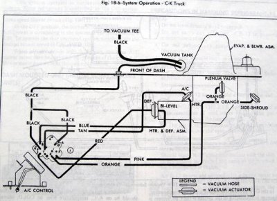
The HVAC control system has only one section of tubing that passes through the firewall and enters the engine compartment. The engine side is connected to the primary vacuum source. The source supply can be taken directly from the intake manifold or any unported tap on the carburetor.
Whichever source you decide to use, that vacuum is applied to port 1 on the HVAC controller valve.
Although there is only that one section of tubing that leads from the controller and passes into the engine compartment, once on the engine side it has a branch line. The branch line is connected to the main line with a tee (or Y fitting) and is lead over to the vacuum reservoir tank.
Another critical component is the check valve. It is inserted into the main line. Be aware that it must be located in the section of tubing that runs between the vacuum source and the point where the line to the vacuum tank is branched off.
A couple of images showing what I mean. Blue is vacuum source applied to both the controller and tank, yellow is flow in and out of the tank (explained below) and red is vacuum (from either the tank or manifold) applied to the controller:
Description of vacuum tank and check valve operation - in response to a question of whether the check valve is necessary:
If that check valve is damaged, does it absolutely have to be replaced, or can you just do a straight shot of vacuum line?
You could do that, but mode control of the HVAC would suffer during periods of low manifold vacuum (e.g. heavy loads/WOT).
The function of the check valve (and the reservoir tank) is to allow for proper operation of the mode control even when no vacuum source is available from the engine. They work together to generate and store a supply of vacuum.
When a deep vacuum is available from the manifold, it is used to operate the diaphragm controlled dampers. The tube that supplies manifold vacuum to the controls is tee'd off in the engine compartment. One side of that tee is lead over to a vacuum tank mounted on the firewall. When manifold pressure is low, a negative pressure is also developed in the vacuum tank. There's also a check valve in the section of tubing that runs from the manifold to the tee. Under ambient conditions, it is held open by a light spring. The spring allows any negative pressure that exists in the manifold to become common with the HVAC control system. Under cruising conditions, that common negative pressure rises and falls slightly - along with any minor fluctuations in engine load/manifold pressure.
But when a heavy load is suddenly applied and the manifold pressure shoots up - the check valve snaps shut. The seal created by the check valve isolates the two sides of the system. On one side is the vacuum stored in the tank (along with any vacuum currently in the control system). On the other side is the higher pressure air in the hose that is connected to the manifold. Without that check valve installed, the higher pressure air on the manifold side of the system would be able to rush in to the HVAC side - operating vacuum would be lost.
The volume of the tank is such that, with the check valve closed, it is able to supply the HVAC controls with sufficient vacuum for full operation. How long it can do that depends on the degree of leakage in the control tubing. But it is designed to provide operation for a reasonable amount of time.
When you let off the accelerator, the throttle plates close down and the pressure in the manifold starts to drop. Now, with the throttle plates trimmed down, the pressure in the HVAC control system eventually rises above manifold pressure (or the manifold pressure drops below the HVAC pressure - whichever way you want to look at it). Either way, at some point the check valve opens. When that happens, the higher pressure air in the control system will begin to flow towards the engine. Eventually the pressure differential between the two systems will reach equilibrium - at manifold pressure. After that, the HVAC side will kind of float along with the manifold side - until the next low engine vacuum event.
Sometimes - because the HVAC controls are operated by vacuum rather than pressure - it's difficult to visualize the direction of flow. Also, in theory there should be no net flow, just the back and forth motion of the air in the tubing. It's kind of like AC power. The only actual flow of air - through the vacuum supply hose to the manifold - is what leaks into the system on the HVAC side. The arrow on the check valve should point in the direction of flow; towards the intake manifold.
Whichever source you decide to use, that vacuum is applied to port 1 on the HVAC controller valve.
Although there is only that one section of tubing that leads from the controller and passes into the engine compartment, once on the engine side it has a branch line. The branch line is connected to the main line with a tee (or Y fitting) and is lead over to the vacuum reservoir tank.
Another critical component is the check valve. It is inserted into the main line. Be aware that it must be located in the section of tubing that runs between the vacuum source and the point where the line to the vacuum tank is branched off.
A couple of images showing what I mean. Blue is vacuum source applied to both the controller and tank, yellow is flow in and out of the tank (explained below) and red is vacuum (from either the tank or manifold) applied to the controller:
You must be registered for see images attach
You must be registered for see images attach
Description of vacuum tank and check valve operation - in response to a question of whether the check valve is necessary:
If that check valve is damaged, does it absolutely have to be replaced, or can you just do a straight shot of vacuum line?
You could do that, but mode control of the HVAC would suffer during periods of low manifold vacuum (e.g. heavy loads/WOT).
The function of the check valve (and the reservoir tank) is to allow for proper operation of the mode control even when no vacuum source is available from the engine. They work together to generate and store a supply of vacuum.
When a deep vacuum is available from the manifold, it is used to operate the diaphragm controlled dampers. The tube that supplies manifold vacuum to the controls is tee'd off in the engine compartment. One side of that tee is lead over to a vacuum tank mounted on the firewall. When manifold pressure is low, a negative pressure is also developed in the vacuum tank. There's also a check valve in the section of tubing that runs from the manifold to the tee. Under ambient conditions, it is held open by a light spring. The spring allows any negative pressure that exists in the manifold to become common with the HVAC control system. Under cruising conditions, that common negative pressure rises and falls slightly - along with any minor fluctuations in engine load/manifold pressure.
But when a heavy load is suddenly applied and the manifold pressure shoots up - the check valve snaps shut. The seal created by the check valve isolates the two sides of the system. On one side is the vacuum stored in the tank (along with any vacuum currently in the control system). On the other side is the higher pressure air in the hose that is connected to the manifold. Without that check valve installed, the higher pressure air on the manifold side of the system would be able to rush in to the HVAC side - operating vacuum would be lost.
The volume of the tank is such that, with the check valve closed, it is able to supply the HVAC controls with sufficient vacuum for full operation. How long it can do that depends on the degree of leakage in the control tubing. But it is designed to provide operation for a reasonable amount of time.
When you let off the accelerator, the throttle plates close down and the pressure in the manifold starts to drop. Now, with the throttle plates trimmed down, the pressure in the HVAC control system eventually rises above manifold pressure (or the manifold pressure drops below the HVAC pressure - whichever way you want to look at it). Either way, at some point the check valve opens. When that happens, the higher pressure air in the control system will begin to flow towards the engine. Eventually the pressure differential between the two systems will reach equilibrium - at manifold pressure. After that, the HVAC side will kind of float along with the manifold side - until the next low engine vacuum event.
Sometimes - because the HVAC controls are operated by vacuum rather than pressure - it's difficult to visualize the direction of flow. Also, in theory there should be no net flow, just the back and forth motion of the air in the tubing. It's kind of like AC power. The only actual flow of air - through the vacuum supply hose to the manifold - is what leaks into the system on the HVAC side. The arrow on the check valve should point in the direction of flow; towards the intake manifold.
Last edited:
chengny
Full Access Member
- Joined
- Feb 22, 2012
- Posts
- 4,084
- Reaction score
- 1,055
- Location
- NH
- First Name
- Jerry
- Truck Year
- 1986
- Truck Model
- K3500
- Engine Size
- 350/5.7
That's what's on the driver's side of the firewall, but I think it was originally for something else. I was going to run a vacuum line to it, but there is only one place to plug in on it (on top), and it looks like the fitting is broken off. There's nothing on my firewall between the blower motor and evaporator coil.
I'm guessing, but for the reservoir to hold vacuum, part #3 would have to be a check valve, and the vacuum line (#4) would have to split to connect to the reservoir and be the vacuum supply line that connects to the rear of the Heater/AC control panel in the cab?
The vacuum reservoir only has one nipple for a connection. The tank is designed to be mounted with connection on the bottom. But - if for some reason - it ever needs to be changed, it is often mounted upside down. The reason is because the factory mount location is very close to the wheel housing (inner fender).
Notice the upper mounting hole on the one pictured:
You must be registered for see images attach
- it's slotted. The one on the bottom isn't slotted. That tank is mounted correctly. The problem is, when reinstalling one of these, it is extremely difficult to get a socket/nutdriver on the lower screw.
So what people do is; without the tank in place, they put the bottom screw into the firewall and bring it up until the gap is just a bit bigger than the thickness of the mounting flange. Then they invert the tank, slip the slot down over the lower screw and drive the upper screw home.
And as far as your thoughts on the configuration/routing of the vacuum system in the engine compartment...perfect. Just be aware of the proper flow direction through the check valve.
bwilhite1
Member
- Joined
- May 14, 2015
- Posts
- 39
- Reaction score
- 8
- Location
- al
- First Name
- bruce
- Truck Year
- 1986
- Truck Model
- k10
- Engine Size
- 350
The vacuum reservoir only has one nipple for a connection. The tank is designed to be mounted with connection on the bottom. But - if for some reason - it ever needs to be changed, it is often mounted upside down. The reason is because the factory mount location is very close to the wheel housing (inner fender).
Notice the upper mounting hole on the one pictured:
You must be registered for see images attach
- it's slotted. The one on the bottom isn't slotted. That tank is mounted correctly. The problem is, when reinstalling one of these, it is extremely difficult to get a socket/nutdriver on the lower screw.
So what people do is; without the tank in place, they put the bottom screw into the firewall and bring it up until the gap is just a bit bigger than the thickness of the mounting flange. Then they invert the tank, slip the slot down over the lower screw and drive the upper screw home.
And as far as your thoughts on the configuration/routing of the vacuum system in the engine compartment...perfect. Just be aware of the proper flow direction through the check valve.
I guess that one had been removed. The slot was on the bottom.
I replaced the AC in the truck a couple of weeks ago. It hadn't been hooked up in years. It's blowing cold off the evaporator coils, but the air out of the floor vent (none is making it to the dash vents) is getting mixed with heat. Obviously, the doors in the heater box aren't moving without vacuum, but I'm also missing the heater water control valve. It looks like that's vacuum powered as well. Is it controlled by the AC controller in the cab as well? I don't see it on this vacuum diagram.
Attachments
chengny
Full Access Member
- Joined
- Feb 22, 2012
- Posts
- 4,084
- Reaction score
- 1,055
- Location
- NH
- First Name
- Jerry
- Truck Year
- 1986
- Truck Model
- K3500
- Engine Size
- 350/5.7
I replaced the AC in the truck a couple of weeks ago. It hadn't been hooked up in years.
It's blowing cold off the evaporator coils, but the air out of the floor vent (none is making it to the dash vents) is getting mixed with heat. Obviously, the doors in the heater box aren't moving without vacuum,
The temperature valve (aka blend door) - item 3 below - is not vacuum controlled:
The position of the damper is moved by a cable. The cable runs from the temperature setting lever on the control panel
to a crank arm on the top of the air handler:
The crank arm is connected to a rod that indexes to change the position of the door:
The blend door as seen from the air exiting the evaporator.
In the cold position - no air flow to the heater core = no reheating:
In full hot - with all the air directed to the heater core and being reheated:
but I'm also missing the heater water control valve. It looks like that's vacuum powered as well. Is it controlled by the AC controller in the cab as well? I don't see it on this vacuum diagram.
There is no flow control valve in the heater hoses or anywhere else in the system. Temperature control is done with the blend door - which varies the percentage of air allowed to flow through the heater core for reheating.
All incoming air first passes over the evap coils (regardless of whether the refrigeration portion of the system is in operation). The operator adjusts the temp of the air issuing from the vents by varying the position of the blend door. This is done by moving the temperature slide lever on the control panel.
It's blowing cold off the evaporator coils, but the air out of the floor vent (none is making it to the dash vents) is getting mixed with heat. Obviously, the doors in the heater box aren't moving without vacuum,
The temperature valve (aka blend door) - item 3 below - is not vacuum controlled:
You must be registered for see images attach
The position of the damper is moved by a cable. The cable runs from the temperature setting lever on the control panel
You must be registered for see images attach
You must be registered for see images attach
You must be registered for see images attach
to a crank arm on the top of the air handler:
You must be registered for see images attach
The crank arm is connected to a rod that indexes to change the position of the door:
You must be registered for see images attach
The blend door as seen from the air exiting the evaporator.
In the cold position - no air flow to the heater core = no reheating:
You must be registered for see images attach
In full hot - with all the air directed to the heater core and being reheated:
You must be registered for see images attach
but I'm also missing the heater water control valve. It looks like that's vacuum powered as well. Is it controlled by the AC controller in the cab as well? I don't see it on this vacuum diagram.
There is no flow control valve in the heater hoses or anywhere else in the system. Temperature control is done with the blend door - which varies the percentage of air allowed to flow through the heater core for reheating.
All incoming air first passes over the evap coils (regardless of whether the refrigeration portion of the system is in operation). The operator adjusts the temp of the air issuing from the vents by varying the position of the blend door. This is done by moving the temperature slide lever on the control panel.