
crazy4offroad
Equal Opportunity Destroyer
- Joined
- Jul 30, 2010
- Posts
- 8,494
- Reaction score
- 1,151
- Location
- West BY-GOD Virginia
- First Name
- Curt
- Truck Year
- 1979
- Truck Model
- K-10
- Engine Size
- 350/SM465/NP205
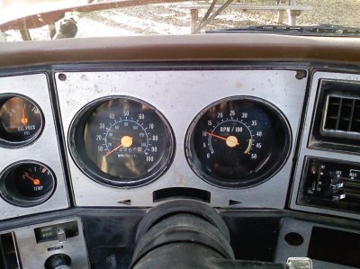
OK when you know you're over your head sometimes you just gotta admit it. I can do a lot of things for an electrical problem but there are some things beyond my knowledge, which is why I started this thread. Here I will post pics of my tach and see if I can arrive at a working tach by the end, and hopefully this thread will be chocked full of info for others in the future.
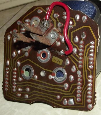
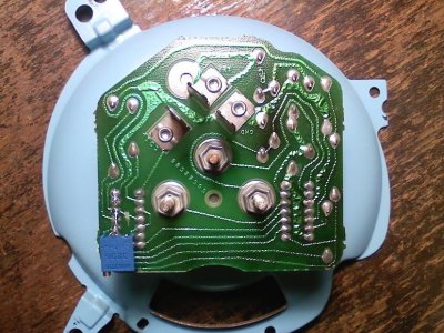
First thing I noticed upon inspection was a burnt circuit on the circuit board. Always look for the obvious first, sometimes it can be something simple. I trimmed back the burnt circuit to the positive (+) post, then soldered in a jumper wire from the positive post to where it was supposed to go...

Re-assembled and tested, and it did not fix it. Instead of reading 1500 RPMs with no response to throttle, it now read 2500 RPMs with no response to throttle. The next resistor in line from the (+) shows zero ohms of resistance so I'm partly wondering if it may be bad, too early to tell though. It could be a diode instead of a resistor, which I believe works like a check valve to prevent back feeding of voltage.
Next came research lol. After many google searches with different terms, the best thing I could come up with was this page on "GM Tach Repair"...
http://www.howtoalmanac.com/kevin/projects/automotive/tachfix.htm
Jumping the gun, I went ahead and ordered the 500k ohm 12-turn potentiometer described in the write-up, when I should have paid attention to the graphic at the top of the page that shows the tach still responds to throttle. I have doubts the method outlined in that write-up will fix this tach. Down the page he makes this statement...
"The tachometer system uses a National Semiconductor LM181 with a GM part number on it. if your tach is completely dead you can replace this chip with the NTE01670 as the LM181 is no longer manufactured. this is the other chip that is completely black. not to be confused with the resistor chip. if your tach works at all the LM181 is fine."
Which is kind of leading me to believe this could be what's wrong with mine. This lead me to finding info on the LM181 air core meter driver (closest I could find is the LM1819) and I found this PDF tech sheet on it...
http://www.ti.com/lit/ds/symlink/lm1819.pdf
Since it is obsolete it also lead me to find this PDF tech sheet on the NTE01670 integrated circuit air core meter driver...
http://www.nteinc.com/specs/1600to1699/pdf/nte1670.pdf
So now I have a couple schematics to do some testing. I have a computer power supply I modified to use as a 12v 18 amp power source for testing. It has built-in power protection and when I hooked it up to the (+) and (-) of the tach the circuit protection tripped in the PSU. Now I'm wondering if something is shorting out on the tach's circuit board.
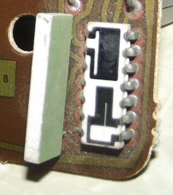
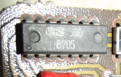
Near as I can tell, the write-up at the howtoalmanac.com website above outlining the resistor chip, this is the chip on my board...

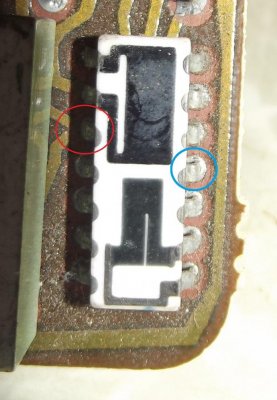
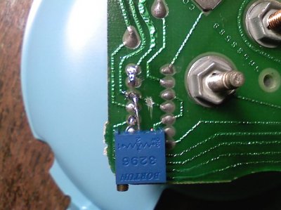
The pin described as having 2 leads going to it (#10) is circled in red below, and #4 circled in blue...

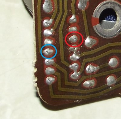
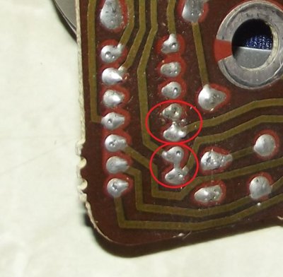
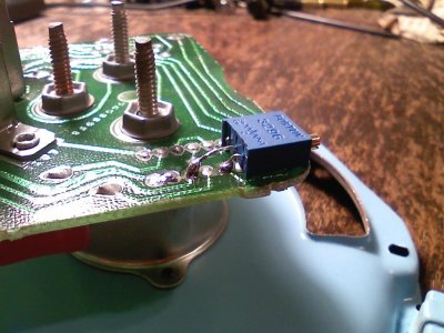
IF it turns out the potentiometer is required I am thinking these are the 2 pins to work with. The flipside of the chip looks like this, remember it is reversed and the circles are correct...

The thing that concerns me about this chip is the solder joints on two sets of pins seem to be touching, and I'm not sure if they are supposed to, circled in red below...

So now I have some testing to do. I will try to verify the LM181 is good, and get an ohm reading for pins 4 and 10 on the resistor chip, and post back the progress later...
First thing I noticed upon inspection was a burnt circuit on the circuit board. Always look for the obvious first, sometimes it can be something simple. I trimmed back the burnt circuit to the positive (+) post, then soldered in a jumper wire from the positive post to where it was supposed to go...
Re-assembled and tested, and it did not fix it. Instead of reading 1500 RPMs with no response to throttle, it now read 2500 RPMs with no response to throttle. The next resistor in line from the (+) shows zero ohms of resistance so I'm partly wondering if it may be bad, too early to tell though. It could be a diode instead of a resistor, which I believe works like a check valve to prevent back feeding of voltage.
Next came research lol. After many google searches with different terms, the best thing I could come up with was this page on "GM Tach Repair"...
http://www.howtoalmanac.com/kevin/projects/automotive/tachfix.htm
Jumping the gun, I went ahead and ordered the 500k ohm 12-turn potentiometer described in the write-up, when I should have paid attention to the graphic at the top of the page that shows the tach still responds to throttle. I have doubts the method outlined in that write-up will fix this tach. Down the page he makes this statement...
"The tachometer system uses a National Semiconductor LM181 with a GM part number on it. if your tach is completely dead you can replace this chip with the NTE01670 as the LM181 is no longer manufactured. this is the other chip that is completely black. not to be confused with the resistor chip. if your tach works at all the LM181 is fine."
Which is kind of leading me to believe this could be what's wrong with mine. This lead me to finding info on the LM181 air core meter driver (closest I could find is the LM1819) and I found this PDF tech sheet on it...
http://www.ti.com/lit/ds/symlink/lm1819.pdf
Since it is obsolete it also lead me to find this PDF tech sheet on the NTE01670 integrated circuit air core meter driver...
http://www.nteinc.com/specs/1600to1699/pdf/nte1670.pdf
So now I have a couple schematics to do some testing. I have a computer power supply I modified to use as a 12v 18 amp power source for testing. It has built-in power protection and when I hooked it up to the (+) and (-) of the tach the circuit protection tripped in the PSU. Now I'm wondering if something is shorting out on the tach's circuit board.
Near as I can tell, the write-up at the howtoalmanac.com website above outlining the resistor chip, this is the chip on my board...
The pin described as having 2 leads going to it (#10) is circled in red below, and #4 circled in blue...
IF it turns out the potentiometer is required I am thinking these are the 2 pins to work with. The flipside of the chip looks like this, remember it is reversed and the circles are correct...
The thing that concerns me about this chip is the solder joints on two sets of pins seem to be touching, and I'm not sure if they are supposed to, circled in red below...
So now I have some testing to do. I will try to verify the LM181 is good, and get an ohm reading for pins 4 and 10 on the resistor chip, and post back the progress later...