6.2 Engine Harness Repair or Replacement?

Disclaimer: Links on this page pointing to Amazon, eBay and other sites may include affiliate code. If you click them and make a purchase, we may earn a small commission.

Milblazer

Full Access Member
Joined
Mar 21, 2013
Posts
268
Reaction score
5
Location
Colorado
First Name
MilBlazer
Truck Year
1984
Truck Model
K5
Engine Size
6.2
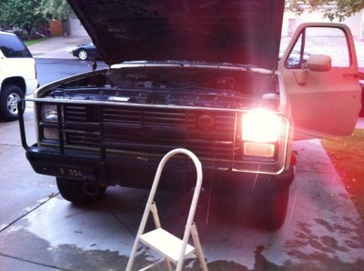
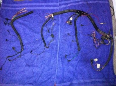
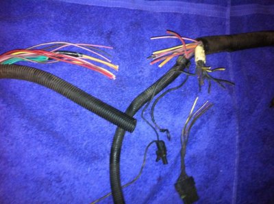
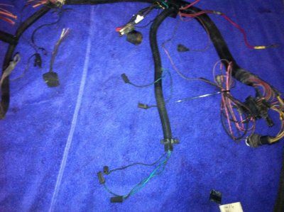
I was wandering through my local pull and pay when I spotted a 6.2 diesel sitting on the tailgate of a K5 Blazer. I wandered over to it and surprisingly the dash harness and engine harness were still on the vehicle. Rushed out to the car to get my tools and came back to grab the two. The dash harness is in very good condition with only a few missing connectors which I have acquired replacements for. The engine harness...that's a different story. It appears someone cut it in half trying to get the injector pump out? That really ticked me off as it was fully loaded. Cruise control, power locks, power windows, A/C.

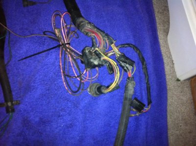
Anyhow, this is the harness I grabbed and I'm wondering if I should repair it or find another. It is pretty much complete just hacked up. These things are pretty hard to come by so any help will be greatly appreciated.
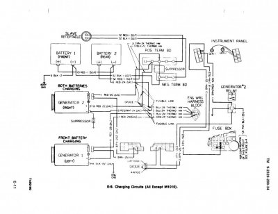
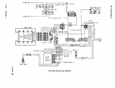
 

Attachments

  • photo 2.jpg
    photo 2.jpg
    98.3 KB · Views: 92
  • photo 3.jpg
    photo 3.jpg
    96.6 KB · Views: 104
  • photo 4.jpg
    photo 4.jpg
    95.7 KB · Views: 96
  • photo 5.jpg
    photo 5.jpg
    96.9 KB · Views: 93

chengny

Full Access Member
Joined
Feb 22, 2012
Posts
4,086
Reaction score
1,010
Location
NH
First Name
Jerry
Truck Year
1986
Truck Model
K3500
Engine Size
350/5.7
I just spliced virtually every wire in a complete power lock/window harness in similar condition. It's not so difficult to do a good permanant repair.

The "master mechanic" that owned the donor truck was selling the door shells to someone else.

Even though I had told him I would surgically remove the harness from the doors, he couldn't wait. By the time I arrived he had used a sawzall to cut through the power L/W wiring harness.

Just take your time and lay the harness out and strip all the ends of the cut wires at once. It is well worth the money to get one of these:

You must be registered for see images attach


It makes the job go so much faster and easier you'll never use a manual stripper again.

Also have on hand a whole new coil of solder, a good Weller gun and sufficient heatshrink tubing in various sizes as dictated by the size of the wires. Buy or borrow a heat gun to shrink the tubing.

Try to stagger the location of the splices so as to avoid big fat snake-bellies in your final product.

Keep the length of the soldered splices as short as possible - you don't want long sections of inflexible leads, they are prone to chaffing through the heatshrink tubing.


Twist the ends of all your wires to be spliced. Then cold splice them in groups. Cross the ends over each other and twist hard enough so they stay attached as you begin soldering.

DO NOT FORGET TO SLIP THE HEAT SHRINK TUBING ONTO THE WIRE BEFORE YOU SOLDER THE ENDS! That is a note to myself.

When you have finshed soldering a group of leads together, slide the heat shrink over the splice and heat gun it in place.

I had 40-50 splices to do and it took me about 3 hours.
 

Milblazer

Full Access Member
Joined
Mar 21, 2013
Posts
268
Reaction score
5
Location
Colorado
First Name
MilBlazer
Truck Year
1984
Truck Model
K5
Engine Size
6.2
Tons of info I didn't even think of. I like the staggering idea. Thank you! What kind of solder should I use? I've heard rosin core is good for automotive wiring. Do the connections where two wires have been soldered ever break? Considering this will be in an engine bay it will be hot and there will be vibrations, anything I should consider just for that?
 

sticman

Junior Member
Joined
Apr 20, 2013
Posts
26
Reaction score
4
Location
Langley BC Canada
First Name
Jason
Truck Year
1980 /1987
Truck Model
K10 / V10
Engine Size
350 5.7L TPI
I'm a fan of 60/40 rosin core solder (sn60pb40) due to my background.

There's all sorts of tin, silver, and lead ratios. More tin equals stronger joint. Stay away from plumbing solder if you can, way too much lead unless its a 50/50 mix.

If you use any solid core solder you will need a tin of flux. I would suggest a tin of flux anyways because just about every old auto harness Ive worked on has oxidized deep into the sheathed cable. Rosin core usually has enough flux to do the job, but nothing will stick to oxidized wire with any amount of heat. Thus the tin of flux comes in to play. Brown to black equals oxidized just like old pennies.

There's new lead free solder on the market that I'm not a fan of and would stay away from as well. It works but is way harder to tell if the finished joint is good to the naked eye and prep is extra important with this stuff. More work with old wire.

The strippers suggested by chenguy are mint for these old harnesses as the plastic sheathing has gotten hard over the years and can be a real bull horn in the ass.

For soldering pencils / guns stay away from anything less the 45 watts. 45 watts is just enough heat to join 14awg with some patience. More wattage makes more heat and easier to work with larger wire sizes, too much heat makes the plastic sheathing melt and recede up the cable away from the heat. Thus you must work quicker with more heat and smaller wire.

Easy once you get the hang of it.
 

chengny

Full Access Member
Joined
Feb 22, 2012
Posts
4,086
Reaction score
1,010
Location
NH
First Name
Jerry
Truck Year
1986
Truck Model
K3500
Engine Size
350/5.7
I just get 2 oz of 60/40 clear flux solder from Radio Shack - the .063" diameter works well.

That 2 oz roll will do your repair and still have plenty left for the future.

Accepted marine environment splice taping procedure (similar to under hood condtions):

Taping Splices

In the December/January Edition of Uptime, the failed splice insulation systems consisted of crimped insulated lugs and vinyl electrical tape-only insulation systems. This is of primary concern as we often see electricians carrying only the vinyl electrical tape in their kits. The other issue is the size of the splice insulation system when taped. Some have almost no insulation on them while others will be a fist-sized ball of tape.

When pigtail-splicing kits are not available, taping systems can be used as a method for insulating your connections. However, the proper method of taping requires three types of tapes to be applied:

1. Varnished cambric – preferably non-adhesive. If there is adhesive, it should be faced outwards during taping;
2. Rubber insulating tape; and,
3. Vinyl electrical tape.

The first step is to apply two layers of varnished cambric tape. This provides a barrier to sharp edges of the connection in addition to electrical insulation. The next layer should be four half-lap layers of rubber tape. During application a constant tension should be applied so that the rubber tape bonds to itself, which is a moisture barrier. Over top of the rubber tape two half-lap layers of vinyl electrical tape is applied and should extend at least 1 inch below the rubber tape along the feeder conductor(s) and motor lead(s). The vinyl tape should also have tension applied as it is wrapped so that it conforms to the layers underneath and has a good seal against moisture and contaminants while also providing an armor jacket to the other layers.


That procedure is overkill but the fundamentals are sound. You can skip the cambric and substitute friction tape for the rubber. One wrap of 3M (or Scotch) friction tape under another wrap of Scotch Super 33+ will last forever.

PRODUCT DESCRIPTION
Helps deliver abrasion protection for splices and connectors with the 3M 3/4 in. x 20 ft. Black Friction Tape. This friction tape can be torn by hand and offers a clean grip.

•Helps provide abrasion protection for splices and connectors
•Reduces motion
•Tears by hand
•Clean grip
•20 ft. long
•MFG Model # : 3407NA-BA-6
•MFG Part # : 3407
 

Attachments

  • 10981928-b9b5-4168-8f40-b860db5e08aa_300.jpg
    10981928-b9b5-4168-8f40-b860db5e08aa_300.jpg
    14.1 KB · Views: 162
  • 4.jpg
    4.jpg
    28.6 KB · Views: 170
Last edited:

towjoe

Full Access Member
Joined
Jul 22, 2012
Posts
695
Reaction score
136
Location
Lafayette,IN
First Name
joe
Truck Year
78,80,81,81,86,88,89
Truck Model
K30's or V3500's
Engine Size
6.2, 454
does anyone have the wiring schematic for one of these military trucks by chance? I'm looking for some info on the glow plugs and I have another one that someone half way convereted to 12 volt.
 

chengny

Full Access Member
Joined
Feb 22, 2012
Posts
4,086
Reaction score
1,010
Location
NH
First Name
Jerry
Truck Year
1986
Truck Model
K3500
Engine Size
350/5.7
Yeah, I have the entire maintenance manual for the CUCV series trucks. It is 1024 pages long.

Here are the wiring diagrams for the M1010 and except M1010 systems.
 

Attachments

  • Glow Plugs except M1010.pdf
    36.5 KB · Views: 141
  • Glow Plugs M1010.pdf
    34.4 KB · Views: 120
  • Glow Plugs except M1010.jpg
    Glow Plugs except M1010.jpg
    86.1 KB · Views: 99
  • Glow Plugs M1010.jpg
    Glow Plugs M1010.jpg
    87.4 KB · Views: 99

chengny

Full Access Member
Joined
Feb 22, 2012
Posts
4,086
Reaction score
1,010
Location
NH
First Name
Jerry
Truck Year
1986
Truck Model
K3500
Engine Size
350/5.7
Mr. Moderator:

Please post this link where you deem most useful - it is the source for the CUCV shop manual (along with some other things):

http://brochures.slosh.com/

It is a non-commercial site that started as a place to download old Chevy GMC sales brochures but has grown. I has a lot of useful info on GMC/Chevy trucks.

For example, I picked a random catagory - frame and body dimensions. Here is what is available for download:

Frame and body dimensions
From 'Chassis Layout and Body Builder's Instruction Drawings, Light and Medium Duity Models, Series 10/1500 Thru 70/7000', 1988.
The book was intended for aftermarket companies building e.g. utility bodies or other add-ons to the GM truck line. I've only scanned the pages to the Blazer/Jimmy, Suburban and pickup. These included body and frame dimensions, should you wish to check your frame for damage, body for misalignment, make CAD models in your free time, or do crazy modifications to your truck that I can only dream of :) Note that pages are oversize and barefly fit on my scanner; they're also large images, to provide greater legibility of the numbers.

These will be basically accurate for all trucks 1973-87/91, with the exception of the 73-77 Blazer floor tub change.

For the pickups, the 131.5" wheelbase is the regular longbed; the 135.5" and 159.5" are cab-and-chassis models. The Crew/Bonus cabs had a 164.5" wheelbase with or without the bed. No information was given for the 117.5" (shortbed) wheelbase.

Published September 1987 for the 1988 model year.

Pickup, single cab, 135.5" and 159.5" WB, 2WD, 1/2
Pickup, single cab, 135.5" and 159.5" WB, 2WD, 2/2
Pickup, Crew/Bonus cab, 164.5" WB, 2WD, 1/2
Pickup, Crew/Bonus cab, 164.5" WB, 2WD, 2/2
Pickup, Crew/Bonus cab, 164.5" WB, 4WD, 1/2
Pickup, Crew/Bonus cab, 164.5" WB, 4WD, 2/2
Pickup, single cab, 131.5", 135.5", 159.5" WB, 4WD 1/2
Pickup, single cab, 131.5", 135.5", 159.5" WB, 4WD 2/2
Pickup, single cab
Pickup, Crew/Bonus cab
Pickup, Fleetside body
Pickup, Crew/Bonus cab
Blazer/Jimmy, 1/2
Blazer/Jimmy, 2/2
Suburban, 1/2
Suburban, 2/2
 
Last edited:

chengny

Full Access Member
Joined
Feb 22, 2012
Posts
4,086
Reaction score
1,010
Location
NH
First Name
Jerry
Truck Year
1986
Truck Model
K3500
Engine Size
350/5.7
Last edited:

Milblazer

Full Access Member
Joined
Mar 21, 2013
Posts
268
Reaction score
5
Location
Colorado
First Name
MilBlazer
Truck Year
1984
Truck Model
K5
Engine Size
6.2
Sorry I haven't replied back, my computer is on the fritz and I have to use my phone to check the forum. Ive purchased a Weller and some solder. Just waiting on my helping hands and some friction tape to get here from amazon. I was wondering if it would be better to heat shrink the connection, then friction tape it, then follow up with some electrical tape? I'll probably start practicing on short strips of wire just so I can get the procedure down as I really don't want to screw this up. Thanks again to everyone who helped me with this project.
 

chengny

Full Access Member
Joined
Feb 22, 2012
Posts
4,086
Reaction score
1,010
Location
NH
First Name
Jerry
Truck Year
1986
Truck Model
K3500
Engine Size
350/5.7
I was wondering if it would be better to heat shrink the connection, then friction tape it, then follow up with some electrical tape?


I'm sorry if I wasn't clear on this - and after reading my post it's obvious that I wasn't.

Only the soldering/heat shrinking procedure is for each individual lead.

It is only after all the splices in a particular area have been completed (i.e. soldered and insulated with heat shrink tubing) does the taping process come into play.

The tape layers are used to wrap the entire bundled group of leads. It isn't necessary to wrap the wires individually.

There would not even be a need to tape the wiring had the soldering not been done.

The tape is not applied to provide extra protection from chaffing against the truck frame, wire clips, etc. The harness loom (the flexible plastic conduit that snaps over the wire bundle) takes care of that.

The primary purpose of the tape is to help stabilize the stiff mechanical joint formed by the soldering procedure. The tendency after doing a group splice is for the inflexible portions of the copper wires, that result from soldering, to rub against each other within the loom.

The tape layer, if done correctly, mechanically locks the wires together so they move in unison. This will prevent independent motion of the wires in relation to each other and consequently prevent chaffing.

Secondary purpose of tape is to add extra protection from ingress of moisture and contaminants. Heatshrink tubing does a good job of this, but not nearly as good as the original insulation.

So you see, taping only becomes necessary when a large number of soldered splices are made adjacent to each other. It is not necessary to tape a single (or even 2-3) wires that have been soldered.

As you do the soldering splice procedure, it will become clear what I mean. You'll notice that the original flexiblity provided by the multi-strand copper wiring group has been lost.

In it's place will be a group of stiff, hard sections of leads that have the ability to cause damage to each other when exposed to normal engine and road vibration.
 

Milblazer

Full Access Member
Joined
Mar 21, 2013
Posts
268
Reaction score
5
Location
Colorado
First Name
MilBlazer
Truck Year
1984
Truck Model
K5
Engine Size
6.2
Well I got everything soldered and heat shrinked. I have a bit of taping and then some cleaning to do. Overall I'm really impressed by how strong of bond soldering provides.
 

chengny

Full Access Member
Joined
Feb 22, 2012
Posts
4,086
Reaction score
1,010
Location
NH
First Name
Jerry
Truck Year
1986
Truck Model
K3500
Engine Size
350/5.7
Yeah, but that strength comes with a cost - the loss of flexibilty that the original stranded copper wire provided.

But, while properly soldering/insulating a large group of wires is time consuming (and does cause some flex loss), it is at a completely different level of repair expertise than what many people resort to - using solderless butt splices.

I bet you never use a butt splice again.
 

Milblazer

Full Access Member
Joined
Mar 21, 2013
Posts
268
Reaction score
5
Location
Colorado
First Name
MilBlazer
Truck Year
1984
Truck Model
K5
Engine Size
6.2
Well its been a while but I got the new engine harness and dash harness installed, along with headlight harness and taillight harness. I was waiting on battery cables and I got those this week. I got everything hooked up and on the second try she started for the first time in a couple months! There are some issues to get to. For instance the rear taillights do not work, only when I step on the brakes do they work. Engine temp gauge and battery voltage are non operational but i'm just glad the thing runs right now. I'll update this as I make progress. I would again like to thank everyone who has helped for getting me this far.
 

Attachments

  • photo.jpg
    photo.jpg
    95.1 KB · Views: 99

chengny

Full Access Member
Joined
Feb 22, 2012
Posts
4,086
Reaction score
1,010
Location
NH
First Name
Jerry
Truck Year
1986
Truck Model
K3500
Engine Size
350/5.7
Make sure you have the correct lamp in the brake/tail lighting sockets.

#2057

But if you are good enough to restore and install a complete engine harness - and it works - I'm sure you have already checked the lamps. Right?
 

Forum statistics

Threads
42,322
Posts
913,644
Members
33,821
Latest member
78ALB
Top