Rag Joint removal faux pas

Disclaimer: Links on this page pointing to Amazon, eBay and other sites may include affiliate code. If you click them and make a purchase, we may earn a small commission.

Frankenchevy

Proverbs 16:18
Joined
Jan 3, 2018
Posts
5,965
Reaction score
7,433
Location
USA
First Name
Jeremy
Truck Year
Square
Truck Model
CUCV
Engine Size
Small
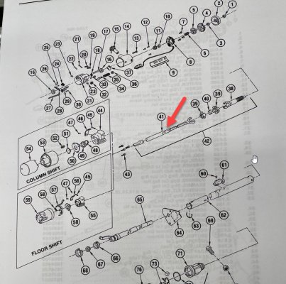
I bought the borgeson u joint steering shaft from ORD and I’m trying to get the upper u joint coupler onto the column side. It wouldn’t freely go on, so first I tried heating up the double D collar to expand it a bit, but couldn’t go too much for fear of damaging the u joint seal. So I’m tapping it on with a brass punch, then all of the sudden the column shaft starts collapsing inward towards the steering wheel. The part with my finger went towards the steering wheel...

Did I just ruin my steering column? I pulled the whole thing out and was able to pull the shaft back to the same depth. Short of pulling the whole thing apart again, I can’t remember what the mechanism is that allows it to collapse in an accident and I’m afraid I sheared that.
You must be registered for see images attach
 

Frankenchevy

Proverbs 16:18
Joined
Jan 3, 2018
Posts
5,965
Reaction score
7,433
Location
USA
First Name
Jeremy
Truck Year
Square
Truck Model
CUCV
Engine Size
Small
There aren’t any burrs on that shaft. I’d already deburred and polished it the first time I worked on the steering shaft when I did the stock components. When I pulled it apart I hit it with 400, then 600 and 1000 to check for rough spots.

If I had a steering wheel pulled this would be a bit easier...
 

Dmack

Full Access Member
Joined
Mar 13, 2019
Posts
311
Reaction score
386
Location
Central OR
First Name
Dave
Truck Year
1983
Truck Model
K20
Engine Size
350
I believe there are a couple of plastic pins that hold the inner and outer column indexed. They were made that way so they would shear easily in a front end collision, allowing it to collapse within itself, and not drive the column into the drivers chest. I don't think it is an issue if you broke them as the column mount and steering box won't allow it to just fall apart.
 

Frankenchevy

Proverbs 16:18
Joined
Jan 3, 2018
Posts
5,965
Reaction score
7,433
Location
USA
First Name
Jeremy
Truck Year
Square
Truck Model
CUCV
Engine Size
Small
I believe there are a couple of plastic pins that hold the inner and outer column indexed. They were made that way so they would shear easily in a front end collision, allowing it to collapse within itself, and not drive the column into the drivers chest. I don't think it is an issue if you broke them as the column mount and steering box won't allow it to just fall apart.
That’s what I imagined they’d be like. Something similar to what the shifter’s sleeve has.
You must be registered for see images attach
 

Frankenchevy

Proverbs 16:18
Joined
Jan 3, 2018
Posts
5,965
Reaction score
7,433
Location
USA
First Name
Jeremy
Truck Year
Square
Truck Model
CUCV
Engine Size
Small
I got it on there. Now I just need to cut the shaft to length.
You must be registered for see images attach
 

Raider L

Full Access Member
Joined
Sep 1, 2020
Posts
1,892
Reaction score
996
Location
Shreveport, LA
First Name
William
Truck Year
1974
Truck Model
C10
Engine Size
355
The part of the steering shaft that connects to the rag joint is the two piece you are referring to? Once there's a hit those two plastic "pins" sheer and the lower shaft attached to the rag joint slides up the solid part of the shaft that goes into the connector housing, that has one end splined facing the end of the steering shaft that's attached to where the shift tube shifts the trans. I'm getting ready to take mine apart, clean all the filthy grease out of it, look at how this works and put it back together.

I'll take pics of this end of the steering so we can understand how that part of the steering shaft can move back and forth inside of the connector housing and still turn with the steering column. I know there is a mechanism inside of it with two plastic "shoes" on it that captures the end of that part of the shaft. The "shoes" fit inside of the shape of the connector housing which does not let the shaft turn independently of them. But what does the end of this end of the shaft look like that keeps it locked between the "shoes" but at the same time let's it slide in and out of that rubber boot at the end of the connector housing?
 

Raider L

Full Access Member
Joined
Sep 1, 2020
Posts
1,892
Reaction score
996
Location
Shreveport, LA
First Name
William
Truck Year
1974
Truck Model
C10
Engine Size
355
Yeah, there's a "pin" in there that goes in a hole in the end of the shaft and that is what has the plastic "bearing blocks" on each end of the pin.

(I just looked in my factory manual at a exploded view of this end of the shaft.)

Yeah, yeah, I know I just killed my own post. I'm old, okay!
 

saltdog

Supporting Member
Supporting Member
Joined
Aug 9, 2020
Posts
35
Reaction score
23
Location
US
First Name
Mike
Truck Year
1983
Truck Model
K20 Suburban
Engine Size
350
@Frankenchevy, I just had the same issue. Are there plastic tabs inside the column than I now need to replace?
 

Frankenchevy

Proverbs 16:18
Joined
Jan 3, 2018
Posts
5,965
Reaction score
7,433
Location
USA
First Name
Jeremy
Truck Year
Square
Truck Model
CUCV
Engine Size
Small
@Frankenchevy, I just had the same issue. Are there plastic tabs inside the column than I now need to replace?

I didn’t end up replacing anything and haven’t had any issues as of yet.
 

saltdog

Supporting Member
Supporting Member
Joined
Aug 9, 2020
Posts
35
Reaction score
23
Location
US
First Name
Mike
Truck Year
1983
Truck Model
K20 Suburban
Engine Size
350
@Frankenchevy cool, and it may never be an issue, but I looked up the parts book illustration and it sure looks like there are some plastic bits in that lower shaft- two nylon pins- very similar to the ones in the stock intermediate shaft to the rag joint. Grr. Guess I'll pull the column just to be sure. Will post findings here
 

Attachments

  • pins.jpg
    pins.jpg
    125.6 KB · Views: 10

saltdog

Supporting Member
Supporting Member
Joined
Aug 9, 2020
Posts
35
Reaction score
23
Location
US
First Name
Mike
Truck Year
1983
Truck Model
K20 Suburban
Engine Size
350
Here are the full parts book illustrations and part lists
 

Attachments

  • IMG_5289.jpg
    IMG_5289.jpg
    212.9 KB · Views: 9
  • IMG_5288.jpg
    IMG_5288.jpg
    146.9 KB · Views: 9
Top