How to fix loose gm steering column

Disclaimer: Links on this page pointing to Amazon, eBay and other sites may include affiliate code. If you click them and make a purchase, we may earn a small commission.

skysurfer

Full Access Member
Joined
Oct 23, 2010
Posts
2,650
Reaction score
2,029
Location
west coast
First Name
John
Truck Year
1989 Suburban
Truck Model
V2500
Engine Size
5.7/TH400/NP241C
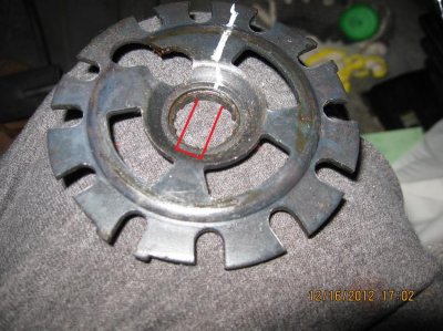
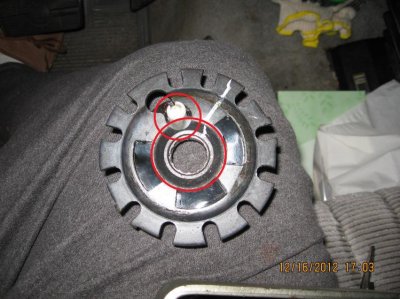
Done deal and everything works. The other end of that toothed slide below the black cam has to be hooked on a pin in the lower part of the steering column, I missed that and also part of the spring has to stick into the large hole in the black piece.

I found it necessary to unhook the wires at the base of the column. There was no way to get the signal switch and housing out of the way without more slack.

You must be registered for see images attach


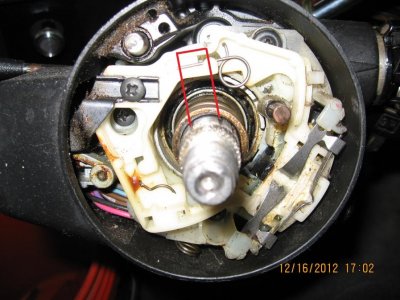
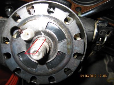
The white connector sits at 6 0'clock and is easy to get to. I had to remove the two bolts holding the metal bracket and drop it down a bit so I could reach the black connector which sits at 3 o'clock on the column. Note the white high beam switch peeking out from 7 o'clock.

Having the panel removed from the lower dash comes in handy when you're doing the reassemby since the high-beam rod falls out of the switch every five seconds.

You must be registered for see images attach


I like to do things on-the-cheap and MacGyver my way through things but this is one job I'm glad I bought the right tools before starting. The locking plate compressor and pivot pin remover got plenty of use and were worth every penny.
 

HotRodPC

Administrator
Staff member
Admin
Joined
Aug 29, 2010
Posts
47,017
Reaction score
9,028
Location
OKC, OK
First Name
HotRod
Truck Year
85 K20 LWB
Truck Model
Silverado
Engine Size
454 - Turbo 400 - 3.73
Cool. I'll need to back track this thread a bit and get up to full speed.

I like that detailed link info, but it would be real cool to have one similar but in squarebody column and make it our own. Of course, I doubt there is that much difference. And we'd actually have close to 4 columns in Squares. Pre Multifunction switch and Post, and Manual with no shifter provisions and Auto, and actually add column shift manual to that too making 6.
 

RetroC10Sport

Supporting Member
Supporting Member
Joined
Sep 29, 2010
Posts
17,094
Reaction score
2,220
Location
Green Bastard Parts Unknown
First Name
Jay
Truck Year
2001
Truck Model
pontiac aztek
Engine Size
3.4
pre '78 had splined end shafts and post 1978 has the D oval shaft.
 

andre.blum

Junior Member
Joined
Sep 15, 2012
Posts
1
Reaction score
0
Location
Willemstad, Curacao
First Name
Andre
Truck Year
1988
Truck Model
1500
Engine Size
5.7
Thank you for this excellent step by step guide!

** Steering wheel **

I bought a cheapo steering wheel puller tool and turned in the center screw manually. It was really tight and the tool's screws began to bend, after which one broke. I had to drill it out. After buying a new screw I decided to use the pneumatic impact wrench, which had no problem with it.


** Pivot pins **

The vise grips trick didn't work too well for me. I had to drill that screw out too, after it broke off real soon.

Instead, I had very good results using the following:

I saw the original tool looks like this:

http://www.etoolcart.com/ProductImages/steering/LIS19940-L.gif

As you can see, it is nothing more than an oversize bus with a nut on a screw (essentially a small version of a pull tool much like the steering wheel pull tool.)

Looking for a nice oversize bus to use, I saw that the large steering wheel nut you removed as one of the first steps was exactly right. If you cover that with a fitting plate ring with a small hole (or a series of ever smaller rings) and then screw in an 8-32 screw with a hex nut, you can turn in the nut and the pivot comes out nice and clean. *if* the screw breaks, it will likely break at a point that leaves enough of the screw out to remove it with the vise grips.

Make sure you center the nut exactly around the pivot pin.

Picture is as it came out, with the pivot pin.
 

Attachments

  • pivottool.jpg
    pivottool.jpg
    95.9 KB · Views: 225
Last edited:

Chop

Junior Member
Joined
Sep 16, 2012
Posts
20
Reaction score
0
Location
Mcminnville
First Name
Randy
Truck Year
1987
Truck Model
c10
Engine Size
5.7
I really need a close up of the high beam linkage and how it goes back together if anyone can get me a pic ...Mine fell out in the floor and i cant for the life of me figure it out
 

89Suburban

Supporting Member
Supporting Member
Joined
Dec 7, 2010
Posts
24,560
Reaction score
5,911
Location
Southeast PA
First Name
Paw Paw
Truck Year
2007
Truck Model
Chevrolet Tahoe LT
Engine Size
5.3, 4WD
I really need a close up of the high beam linkage and how it goes back together if anyone can get me a pic ...Mine fell out in the floor and i cant for the life of me figure it out

I feel your pain. You will have to hang for a while until I can get some pics unless somebody else can help. I have to install one in mine, couldn't get to it this weekend, but I am shooting for next, I'll be sure to document with some extra pics. That pushrod is a pain in the ass to setup correctly. Only tip I can give you right now is make sure the lower end is on the hole for the high beam switch and the upper end should be pointing up.


Here is an outstanding write up on the complete column.

http://www.diyfiero.com/dropspot/Jazzman_Steering_Rack_Rebuild.pdf

Of ****, what the hell happened to this link!!!?? :lazer:
 

Chop

Junior Member
Joined
Sep 16, 2012
Posts
20
Reaction score
0
Location
Mcminnville
First Name
Randy
Truck Year
1987
Truck Model
c10
Engine Size
5.7
I got the high beam back together what a pain in tha !$##....I took it all apart without the spring compressor tool but i think Im going to have to get one ..It got late so i had to stop but I cant see pressing it down enough physically to get the snap ring on .

But thanx to this thread my column is all nice and tight..dash should be here wed.my seat will be finished friday...that will be all the interior work for now.
 

foamypirate

Full Access Member
Joined
Jul 30, 2010
Posts
3,302
Reaction score
453
Location
Central TX
First Name
Jake (Mr. Wilson)
Truck Year
1980
Truck Model
El Camino, baby!
Engine Size
5.3L/4L60E
This step I think is redundant as the lock plate has a key that aligns with the shaft.

It still may not be a bad idea. The lock plate in my 84' had the key removed or ruined somehow. It was on 180* out when I took off the wheel.

EDIT: Curiosity got the best of me, so I took my lock plate off again. The "key" is just spaced two notches apart, but still fits the pattern, so you can install it anywhere, at least with what's on my column and lock plate.
 
Last edited:

hinkv10

Full Access Member
Joined
Nov 8, 2012
Posts
221
Reaction score
9
Location
ct
First Name
craig
Truck Year
1987
Truck Model
v10
Engine Size
350
Help! I'm reassembling the column after replacing the spring for the shifter and tightening the column bolts. I'm stuck trying to put this back together. Any tips?

Then this DAMNED section falls out and apart, a housing section, a plastic push piece, and the steel linkage rod is left dangling, a mystery to me to put back together in working order, more of a mystery than women, and even Retro...

You must be registered for see images

free picture hosting
 

RetroC10Sport

Supporting Member
Supporting Member
Joined
Sep 29, 2010
Posts
17,094
Reaction score
2,220
Location
Green Bastard Parts Unknown
First Name
Jay
Truck Year
2001
Truck Model
pontiac aztek
Engine Size
3.4
Put a little dab of grease or even petroleum jelly on it to keep it in the column housing.
 

89Suburban

Supporting Member
Supporting Member
Joined
Dec 7, 2010
Posts
24,560
Reaction score
5,911
Location
Southeast PA
First Name
Paw Paw
Truck Year
2007
Truck Model
Chevrolet Tahoe LT
Engine Size
5.3, 4WD
Updated pics on the notch issue. On the lock plates and positioning of the cancelling cam. They must be different on certain years, but there is absolutely no way to clock the locking plate on mine except for one position as per the following pics. I also tried to clock the cancelling cam itself under the locking plate into the different openings in the lock plate, it will not center at the center bore of the plate unless it is in the specific circular cut spot as shown. I drew a ring around the opening of the bottom edge of the slots and you can clearly see it cutting part of the horn feed tower. The steering wheel itself can be clocked in any position, but to align with the horn feed tower there is very limited movement avail, like 2 or 3 teeth on the steering wheel hub, and you need to pay attention during assembly of the locking plate that the tower is positioned perfectly where you had it before because there is some play in that hole in the locking plate.
 

Attachments

  • IMG_0302.jpg
    IMG_0302.jpg
    95.5 KB · Views: 225
  • IMG_0303.jpg
    IMG_0303.jpg
    96.8 KB · Views: 236
  • IMG_0304.jpg
    IMG_0304.jpg
    96.9 KB · Views: 221
  • IMG_0306.jpg
    IMG_0306.jpg
    89.4 KB · Views: 221

foamypirate

Full Access Member
Joined
Jul 30, 2010
Posts
3,302
Reaction score
453
Location
Central TX
First Name
Jake (Mr. Wilson)
Truck Year
1980
Truck Model
El Camino, baby!
Engine Size
5.3L/4L60E
Interesting. See how your's has that space between on those splines? Mine isn't like that, it's consistently spaced all the way around. Wonder if I got a reject. :roflbow:
 

Latest posts

Forum statistics

Threads
42,312
Posts
913,503
Members
33,810
Latest member
Garcjay
Top