Adapter between SM465 and NP205

Disclaimer: Links on this page pointing to Amazon, eBay and other sites may include affiliate code. If you click them and make a purchase, we may earn a small commission.

bucket

Super Moderator
Staff member
Super Moderator
Joined
Aug 3, 2010
Posts
29,087
Reaction score
23,894
Location
Usually not in Ohio
First Name
Andy
Truck Year
'77, '78, '79, '84, '88
Truck Model
K5 thru K30
Engine Size
350-454
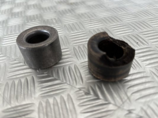
Thanks @bucket! When you say “a means of giving the bolts more room to stretch”, do you mean that the spacers from the factory (installed between the top of the frame and the nut) allow the bolts to be longer than they would be without the spacers? Ok other words, the spacers come from the factory and they are installed between the top of the frame and the nut (with the bolt coming in from the bottom)?

Yes, exactly. A shorter bolt would have been more likely to break due to frame flex.
 

Mark80K15

Full Access Member
Joined
Apr 18, 2021
Posts
86
Reaction score
44
Location
Sicamous, BC
First Name
Mark
Truck Year
1980
Truck Model
K15
Engine Size
350
Ok thanks @bucket, that's good info. I suppose either configuration is structurally the same...
 

Mark80K15

Full Access Member
Joined
Apr 18, 2021
Posts
86
Reaction score
44
Location
Sicamous, BC
First Name
Mark
Truck Year
1980
Truck Model
K15
Engine Size
350
A bit of cautionary advice here: during this project I pulled the engine. I forget if I mentioned that earlier in the post. At this point the NP205, adapter, and SM465 are all bolted together, and earlier this week I installed the engine. Just before installing the engine, I noticed that the pilot busing was damaged. See picture, comparing the damaged one to a new one. This is the bushing that sits in the back of the crankshaft, and the input shaft of the SM465 rides in it. I believe it was damaged for the same reason the bellhousing was cracked. The missing mount under the adapter caused massive misalignment in the whole drivetrain, including misalignment of the SM465 input shaft into the back of the crankshaft. The pilot bushing took all of that abuse (which I suspect it is designed to).

Lesson: whenever the engine is out, replace the pilot bushing. Just because.
 

Attachments

  • worn_pilot_bushing.JPG
    worn_pilot_bushing.JPG
    91.8 KB · Views: 39

Maknwine

Full Access Member
Joined
Nov 24, 2016
Posts
101
Reaction score
141
Location
Virginia
First Name
Tom
Truck Year
1987
Truck Model
c30
Engine Size
5.7
And finally, another question. See the spacers between the top surface of the crossmember and the frame? Is that correct? I'm pretty sure that's how it was when I took it apart, but of course I didn't take pictures and of course I don't remember for sure. Can anyone confirm if they have the same factory setup on their SM465/NP205?
Very good informative thread here. This is obviously late to the game but I'll add in case it helps someone else, the "not taking before pics" happens to me as well but in your second pic you can see the rust imprint so to speak where the trans mount was mounted to the frame which would prove the spacers were on the wrong side. I've used that type of "imprint" before on other things I didn't record before dismantling parts. Usually all trace imprints would be wire brushed, sanded, and rattle canned prior to with my luck....LOL
 

AuroraGirl

Full Access Member
Joined
Sep 8, 2019
Posts
9,206
Reaction score
6,186
Location
Northern Wisconsin
First Name
Taylor
Truck Year
1978, 1980
Truck Model
K10, K25
Engine Size
400(?), 350
Hey, sorry to carry this on, but I still need a little more info. Now that I've pulled the x-member out that the adapter sits on, I only have more questions. Attached are 2 pictures of the x-member out of the truck with the one mount in place. On both pictures, the left is the passenger side.

The first picture is exactly as I found the x-member and mount. There is only one mount, on the passenger side. The front driveshaft attaches to the transfer case on the passenger side also. I don't know if there was ever a mount on the driver's side, but there wasn't one when I took the x-member off.

The second picture shows the same thing, but with the passenger side (upper) mount removed. You can see the broken bolt poking up out of the hole, so for this one mount, the adapter wasn't even bolted on! Just sitting on it. Glad I'm working on this.

So, is there really supposed to be 2 mounts? (I've heard yes and no!). If so, is there any significance that the passenger hole is round but the driver's hole is rounded rectangular? Is it the same mount for both sides? Does anyone have a picture of how the mount(s) bolts to the adapter? Does anyone have a picture of the adapter? Thanks!
You must be registered for see images attach

this is a drivetrain from a 1977 chevy/gmc k20/k25
The only difference between this and the 1980 we both have is the crossmember sits lower here and the adapter is "Taller" than the 1980

The reason I show you this was I dont have my original tcase or trans in my truck, I have a 1986 np208/sm465 combo. Mines in the shed lol. I know you already have this figured out, but pictures never hurt!!
You must be registered for see images attach

Other than the differences i pointed out on the crossmember and the adapter height, the only difference yet to a 1980 would be the 1980 has a slip yoke rear output not a fixed.

heres my 1980 drivetrain:
You must be registered for see images attach
 

Forum statistics

Threads
42,070
Posts
908,404
Members
33,545
Latest member
GrayWK
Top