Wiring diagrams would awesome
@VTXRider
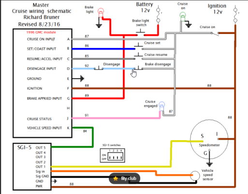
I'll attach the manual, a diagram I used, and an explanation of how I got mine working.
The GM manual is great info and I would recommend reading it all before you start.
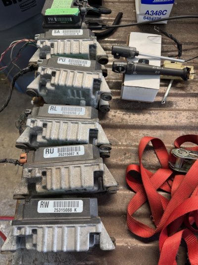
You can bench test the module if you set up the circuits. I did that, and as I said, I have multiple modules that all bench tested good.
The diagram attached is with a Dakota Digital SGI-5 module, which is an older discontinued module.
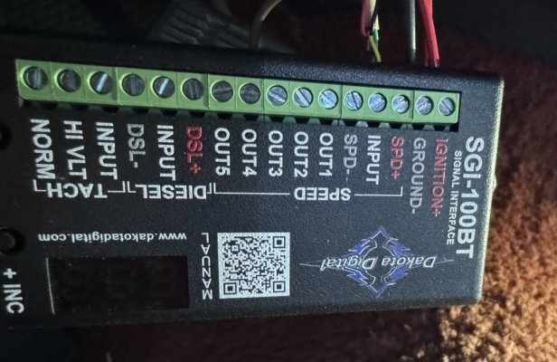
I purchased and used the Dakota Digital SGI-100. It's simple to connect, adjustable and you can monitor the signal.
You need a 4000 pulse per mile square wave signal for the cruise to work, and the SGI-100 provides that. I'll have to get you
a picture of the module and pinouts I used. You will need a signal generator to get a signal to the Dakota Digital module.
There are several aftermarket units out there. I used the one that is inline on my speedo cable that provides a signal for my
Gear Vendors overdrive. You could get one from them. It's an 8000ppm sender, so the DGI-100 adjusts that down to 4000ppm. I just spliced into the signal wiring and plugged that into the SDI-100. The Dakota manual gives you all the info for that, and I'll get you a picture of how I wired mine in.
As you said your truck is a manual, you'll need a clutch switch as well as brake switch inputs. If your brake switch has 2 connectors, you can use those and then just install & wire in a clutch switch. You do need both connectors on the brake switch, as the module needs to "see" the brake light circuit is valid before it will allow cruise control to engage.
One brake circuit provides 12 volts to the brake lights, and cuts the cruise off when you step of the brakes, and the other circuit has 12 volts and goes open when when you step on the brakes.
I'm using LED brake lights and they won't work, so I just wired in a clearance light bulb in the circuit under the hood to test it and get it working. I may swap that out to a resistor down the road, but it's an easy way to check that circuit if needed.
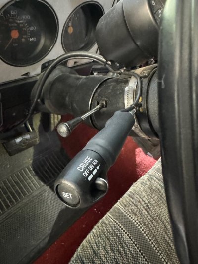
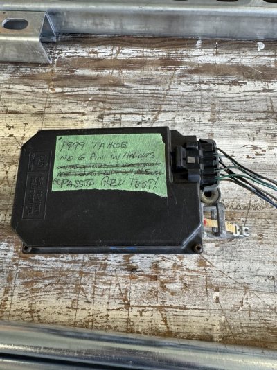
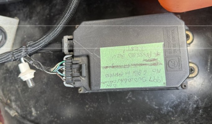
My cc module and stalk switch came off a 1999 Suburban. I took the stalk switch apart, removed the wiper components, rewired it, cut and threaded my old turn signal lever, and threaded the stalk switch on. I didn't take pictures of the process at the time, so sorry about that. Depends on how mechanical and patient you are for that part of the process. I wanted just the cruise switches, and already have a tilt column, so it worked out well.
I also wired in a cruise engaged indicator LED. I had the LED already and it's easy to wire in the circuit.
You only need light gauge wiring for the stalk switch, indicator light, and speed signals, as it's all just signal circuits.
Power and grounds can be 16 gauge as well. I used the old choke circuit for power to the module as it was already in the engine bay, not being used, and ignition controlled.
Once you get your switches in and wiring run to where you are going to mount your module, you can use a DVOM, or a test light if necessary, to check function of all the circuits. DVOM is better so you can see if you have a good ground, and if there are any volt drops on your circuits. The CC module has a 10 pin connector, 9 get used, 1 is left empty and capped with a plug. if you don't wire in the cruise engaged light, then 2 pins are left empty. I have a list of the pin ID's and what to test each circuit for so I'll dig that up as well.
Ok, this is long enough for now. I'll go get some more pictures of my install for you. Hope this all helps out.