Turbo 350 Build

Disclaimer: Links on this page pointing to Amazon, eBay and other sites may include affiliate code. If you click them and make a purchase, we may earn a small commission.

HotRodPC

Administrator
Staff member
Admin
Joined
Aug 29, 2010
Posts
47,014
Reaction score
9,014
Location
OKC, OK
First Name
HotRod
Truck Year
85 K20 LWB
Truck Model
Silverado
Engine Size
454 - Turbo 400 - 3.73
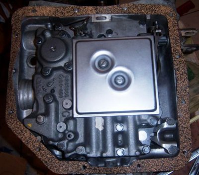
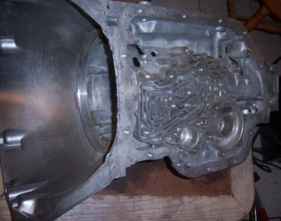
Dab some TransJel in several spots on the valve body channels of the case. Doesn't need to be in globs. Just enough to keep the gasket in place and from moving around.
attachment.php


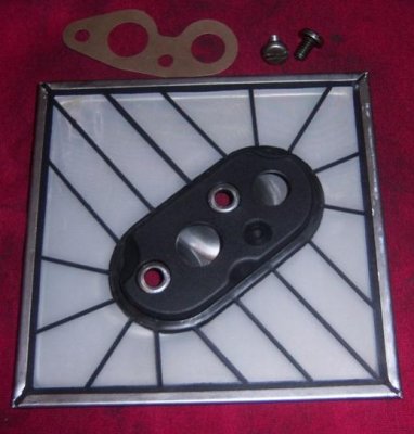
Now set the seperator plate over the case gasket. If you don't wish to hold it in place like I have here, you can start 2-3 valve bolts to hold it in place while you move onto the next step/
attachment.php


With the case gasket and seperator plate held in place, put the valve body gasket and support plate in position and start all the support plate bolts. Do not snug or tigheten them. Just getting them started is good enough to hold all pieces in place. You need to leave them loose for the next step.
attachment.php


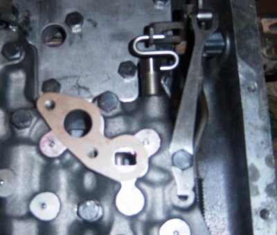
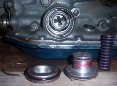
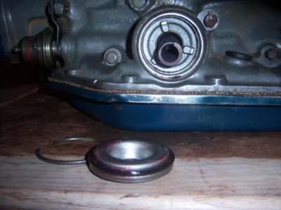
If you put the 2-3 bolts in the valve body area to hold the gaskets in place, remove them now that the support plate bolts will hold them in place. Put the manual valve and S clip in the valve body. While connecting the S link to the manual linkage, set the valve body over the gasket and start all the valve body bolts with exception of the detent spring and roller retaining bolt. You want to save that one til last because the valve body is slightly raised at the accumulator at this point until you have the vavle body snugged to hold the valve body flat. You don't want to force any of these valve body or support plate bolts at all. If they are the least crossed or not straight, they can easily strip the threads from the alluminun case, and then you have another HeliCoil situation. Now that all the bolts but the one are started and snugged, you put the detent spring and roller on the manual linkage. While pushing down on the spring, hand snug the bolt.
attachment.php


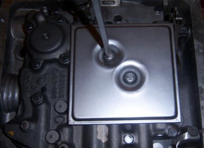
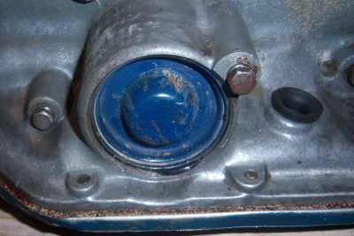
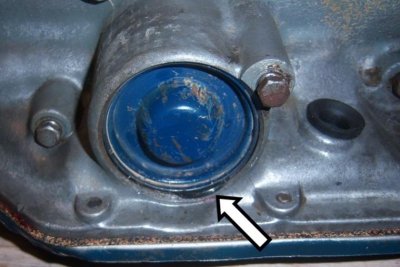
Now that all your support plate and valve body bolts are snugged in place and you feel confident all the gaskets, plates and valve body are in their proper position, torque the bolts to spec of 13ft lbs. I torque them to just over 150 inch lbs with the cheap bar type torque wrench. If any of the bolts give way and do not hold 150in lb, then they have stripped and you will have to HeliCoil those bolt holes just as I had to do on the front pump. Provided you have the linkage assembly installed properly, it should not look like this below.
attachment.php


You must be registered for see images attach


You must be registered for see images attach


You must be registered for see images attach


You must be registered for see images attach


You must be registered for see images attach
 
Last edited:

HotRodPC

Administrator
Staff member
Admin
Joined
Aug 29, 2010
Posts
47,014
Reaction score
9,014
Location
OKC, OK
First Name
HotRod
Truck Year
85 K20 LWB
Truck Model
Silverado
Engine Size
454 - Turbo 400 - 3.73
Just about ready for the pan install now. But first, Install these small parts for the detent cable that goes to the throttle linkage.
attachment.php


Connect the rod to the detent lever. Be sure to thread the rod thru the hole leaving the valve body area. Hold the detent lever in position and slide the retaining pin into position that holds the lever in place.
attachment.php


Be sure to check the outside of the case to make sure the rod is sticking out of the hole where the detent cable will connect. If its not, you will need to find out why. Better to do so now before you put the pan on and torque it in place.
attachment.php


You must be registered for see images attach


You must be registered for see images attach


You must be registered for see images attach
 
Last edited:

HotRodPC

Administrator
Staff member
Admin
Joined
Aug 29, 2010
Posts
47,014
Reaction score
9,014
Location
OKC, OK
First Name
HotRod
Truck Year
85 K20 LWB
Truck Model
Silverado
Engine Size
454 - Turbo 400 - 3.73
One more thing to install before the pan !!!
attachment.php


Dab some TransJel over the filter holes to hold the filter gasket in place.
attachment.php


Set the filter over the gasket install and tighten the 2 screws and the filter is now installed.
attachment.php
 

Attachments

  • th350build 388.jpg
    th350build 388.jpg
    35.2 KB · Views: 451
  • th350build 389.jpg
    th350build 389.jpg
    40.3 KB · Views: 465
  • th350build 390.jpg
    th350build 390.jpg
    50.1 KB · Views: 424
Last edited:

HotRodPC

Administrator
Staff member
Admin
Joined
Aug 29, 2010
Posts
47,014
Reaction score
9,014
Location
OKC, OK
First Name
HotRod
Truck Year
85 K20 LWB
Truck Model
Silverado
Engine Size
454 - Turbo 400 - 3.73
Get the rest of your parts out of the solvent bath or whatever method you used to clean them.
attachment.php


As with most gaskets, use TransJel to hold the pan gasket in place.
attachment.php


Look your pan over real good to make sure its flat and not dented inward. If it is, use a rubber or plastic hammer and beat it out. There is very little clearance between the pan and filter, not to mention the loss of fluid capacity. I did have another pan to use for this build, but this pan has a drain plug in it, which BTW, is a bit uncommon on an OEM pan. So the benefit to use this pan was there and I decided to make it useable.
Lay the pan over the gasket and only start all the bolts so that you can adjust the gasket as necessary. Once all the bolts are in place and you are happy with the location of the gasket, go ahead and snug all bolts.
attachment.php


If I recall, torque specs on the pan is 13ft lbs. I torque cork/rubber gaskets to 175 inch lbs. That does not seem to squish out the side, but tight enough to not leak. I've torqued to 150 inch lbs before and after a couple weeks of use, seem to start leaking. More importantly, do NOT overtighten and squish the gasket or you'll need to replace it in short order along with leaks until you do so.
attachment.php
 

Attachments

  • th350build 397.jpg
    th350build 397.jpg
    62.1 KB · Views: 425
  • th350build 393.jpg
    th350build 393.jpg
    58.8 KB · Views: 429
  • th350build 398.jpg
    th350build 398.jpg
    72.9 KB · Views: 457
  • th350build 404.jpg
    th350build 404.jpg
    41.4 KB · Views: 412
Last edited:

HotRodPC

Administrator
Staff member
Admin
Joined
Aug 29, 2010
Posts
47,014
Reaction score
9,014
Location
OKC, OK
First Name
HotRod
Truck Year
85 K20 LWB
Truck Model
Silverado
Engine Size
454 - Turbo 400 - 3.73
Now for the external components. It doesn't really matter which order you choose to do them in.

I'll start with the vacuum modulator components.
attachment.php


Fairly simple to do. Slide the Vacuum modulator vavle into the case. Make sure its able to move freely. Then put the vacuum modulator in, add the retainer and bolt then tighten to 150 inch lbs.
attachment.php


Now I'll do the governor. I have cleaned the previous silicone off the case. NOTICE, I have not used and type of silicone or sealer thoughout this entire build. NO reason to. Simply torque to spec and the gaskets should do their job fine. You do want to inspect the governor. Make sure the teeth are not chewed on and in good shape. Also make sure the valve moves freely inside the governor.
attachment.php


Apply a little Transjel around the seal and the governor cover flange. Lightly tap the cover into place using a rubber or plastic hammer. I usually tap on the edges around the cover, not the center of the cover. You don't want it dented, or it will rub the governor. Once installed, then snap the retainer into place.
attachment.php
 

Attachments

  • th350build 408.jpg
    th350build 408.jpg
    35.3 KB · Views: 462
  • th350build 409.jpg
    th350build 409.jpg
    33.6 KB · Views: 432
  • th350build 410.jpg
    th350build 410.jpg
    45.2 KB · Views: 432
  • th350build 456.jpg
    th350build 456.jpg
    87.4 KB · Views: 435
Last edited:

HotRodPC

Administrator
Staff member
Admin
Joined
Aug 29, 2010
Posts
47,014
Reaction score
9,014
Location
OKC, OK
First Name
HotRod
Truck Year
85 K20 LWB
Truck Model
Silverado
Engine Size
454 - Turbo 400 - 3.73
Next, lets do the tailshaft housing aka extension housing. Gather the speedometer gear parts and clean them.
attachment.php


Install the speedometer driven gear keeper into the small hole in the output shaft.
attachment.php


Slide the speedometer driven gear over the output shaft and onto the keeper. You have to push the keeper fingers down to start the gear over the keeper. This is pretty tight. You would have to use something very dull, not sharp, like maybe a brass drift or wooden dowel to very lightly tap the gear into place. Keep in mind, its just plastic so be gentle or you will break it.
attachment.php
 

Attachments

  • th350build 415.jpg
    th350build 415.jpg
    59.2 KB · Views: 422
  • th350build 416.jpg
    th350build 416.jpg
    49.2 KB · Views: 404
  • th350build 418.jpg
    th350build 418.jpg
    86.4 KB · Views: 423
Last edited:

HotRodPC

Administrator
Staff member
Admin
Joined
Aug 29, 2010
Posts
47,014
Reaction score
9,014
Location
OKC, OK
First Name
HotRod
Truck Year
85 K20 LWB
Truck Model
Silverado
Engine Size
454 - Turbo 400 - 3.73
Find the square cut O ring for your tailshaft housing in the kit. Replace it as shown on the extension housing. Add a light coat of TransJel. Slide it into position over the output shaft and start all 4 bolts holding the extension housing to the case. Then torque to 35ft lbs or 400 inch lbs.
attachment.php


Find the the O ring and the speedo driver gear seal in your kit. Using a pick, pull the seal out of the end speedo driver gear housing. Add TransJel to both the O ring and the driver gear seal and replace.
attachment.php


Insert the speedo driver gear housing into the extenson housing, add the retainer and bolt and tighten. If you feel the need to torque this one, I'd go with 150 inch lbs.
attachment.php
 

Attachments

  • th350build 420.jpg
    th350build 420.jpg
    48.9 KB · Views: 417
  • th350build 425.jpg
    th350build 425.jpg
    92.5 KB · Views: 419
  • th350build 428.jpg
    th350build 428.jpg
    46.7 KB · Views: 413
Last edited:

HotRodPC

Administrator
Staff member
Admin
Joined
Aug 29, 2010
Posts
47,014
Reaction score
9,014
Location
OKC, OK
First Name
HotRod
Truck Year
85 K20 LWB
Truck Model
Silverado
Engine Size
454 - Turbo 400 - 3.73
I hav lubbed and installed the dipstick seal. Moving ont the 1-2 Accumulator. Gather and clean the parts. Find the round O ring for the accumulator cover, and the new sealing rings for the accumulator piston and carefully install the new sealing rings. They are very brittle and can break. Also add TransJel to the seal, the accumulator piston and the cover.
attachment.php


Install the lubed accumulator piston into the bore. This might take some tapping with a wooden hammer handle to get started. Then put the accumulator spring behind the piston.
attachment.php


Now here is a great example of even those who know what they are doing can screw up !!! Do we see a problem here??? What I did, as you can see in the previous pic, was put the O-Ring on the Accumulator cover. That is how is should be done right? Only makes sense doesn't it??? Well that is WRONG !!! DO NOT PUT the O-Ring over the cover. As I had previously mentioned, its been over 15 years since I built a Th350 and I knew there was a trick to this cover, and I was thinking it was the side hole for inserting a pick to remove it. The second I seen this pinch, I remembered what the trick was !!!
attachment.php
 

Attachments

  • th350build 459.jpg
    th350build 459.jpg
    81.8 KB · Views: 478
  • th350build 460.jpg
    th350build 460.jpg
    71.5 KB · Views: 508
  • th350build 463.jpg
    th350build 463.jpg
    53.2 KB · Views: 507
  • th350build 463-2.jpg
    th350build 463-2.jpg
    54.9 KB · Views: 800
Last edited:

HotRodPC

Administrator
Staff member
Admin
Joined
Aug 29, 2010
Posts
47,014
Reaction score
9,014
Location
OKC, OK
First Name
HotRod
Truck Year
85 K20 LWB
Truck Model
Silverado
Engine Size
454 - Turbo 400 - 3.73
For those who did not catch my mistake in the photo. Here is the same photo with an arrow pointing it out. This would have been a very very bad leak as there is alot of pressure on the accumulator.
attachment.php


Now, I am going to install the 1-2 Accumulator the correct way. Here is the trick. Install the O-Ring into the bore up against the lip where the O ring goes. If you look close inside the bore, you see where the seal goes.
attachment.php


THEN push the accumulator cover into position. Push it in up against the O ring as far as you can to make room for the snap ring. Remember the disassembly hole on the outside of the accumulator bore??? For the hole to be beneficial, you'll want the snap ring end to land about 1/4 to 1/2 inch past the hole. If you put the center of snap ring to the hole, its not going to be very beneficial in getting the snap ring to start coming out of its groove. It happens to be a pretty tough snap ring, so think ahead for yourself or the next guy who may need to remove the cover and put the end of the snap ring in its proper location.
attachment.php


Notice where I landed the snap ring in the pic above in relation to the disassembly hole on the outside of the bore.
attachment.php


Here is a better angle of where I landed the snap ring in relation to the disassembly hole for the 1-2 accumulator. Also notice I have now installed the dipstick tube !!!
attachment.php


You must be registered for see images attach


You must be registered for see images attach


You must be registered for see images attach


You must be registered for see images attach
 
Last edited:

HotRodPC

Administrator
Staff member
Admin
Joined
Aug 29, 2010
Posts
47,014
Reaction score
9,014
Location
OKC, OK
First Name
HotRod
Truck Year
85 K20 LWB
Truck Model
Silverado
Engine Size
454 - Turbo 400 - 3.73
And last but not least. The last item of this build to install is the detent cable, very well known as the kickdown cable.

To install the cable, put the loop over the detent linkage wire.
attachment.php


Then pull the slack at the top of the cable, and this will pull the cable housing into the transmission without binding the linkage. Then snug up the holding bolt and its now ready for installation into the vehicle !!!
attachment.php


You must be registered for see images attach


You must be registered for see images attach
 
Last edited:

HotRodPC

Administrator
Staff member
Admin
Joined
Aug 29, 2010
Posts
47,014
Reaction score
9,014
Location
OKC, OK
First Name
HotRod
Truck Year
85 K20 LWB
Truck Model
Silverado
Engine Size
454 - Turbo 400 - 3.73
WOO HOO !!! And there we go. Finally !!!

attachment.php


And for the next one, already sitting on the table...
attachment.php
 

Attachments

  • th350build 481.jpg
    th350build 481.jpg
    79.3 KB · Views: 431
  • th350build 485.jpg
    th350build 485.jpg
    64.2 KB · Views: 414
Last edited:

HotRodPC

Administrator
Staff member
Admin
Joined
Aug 29, 2010
Posts
47,014
Reaction score
9,014
Location
OKC, OK
First Name
HotRod
Truck Year
85 K20 LWB
Truck Model
Silverado
Engine Size
454 - Turbo 400 - 3.73
And now.... That is finally done, I sure hope someone gets some use out of it. It took much longer than I had ever anticipated. Also really drug out the length of time for the build taking pictures, and cleaning my hands in between shots so I didn't screw up my camera.

I have not gone back over the thread from beggining to end yet to look for mistakes. I am sure there are going to be some. If you look at the time stamps, some of these posts were done at wee hours of the morning, where I stayed up way late, or woke up in the middle of the night and came into the office to work on it. I am not even kidding when I say I fell asleep at the computer slumped over in my chair to wake up in major neck pain. That happened severals times on differant nights. Just one of my ailments I live with. So help me out with any corrections or misspellings that need corrected. For the time invested in this, I want it right, and nothing less than perfect. If pics aren't very accurate or something of that nature, and they are not explanatory enough, let me know. I have more pics. I took 483 pictures for this thread, so I have more pics if needed.

I did do a Th400 build also, but nowhere near the detail as this one. http://www.gmsquarebody.com/forum/showthread.php?t=295

I do like this build, and it was a perfect build for a write up. Reason being, things went wrong like the pump bolt being stipped out. Things were found wrong in the previous build of this transmission and corrected. I even made an honset mistake myself. You might wonder, why I even incuded those things and why I didn't just fix them real time and leave them out of the build thread and go forward. There was a purpose of why they were included. Those are actual things that can go wrong, and things you need to be prepared for when building transmissions. They are real events and they do happen.

Some things I'd like to point out even though I probably mentioned most of them in the thread.
Many times there are special tools required. Sometimes you can improvise, sometimes you can't depending on the model of transmission you are working. Many times when you can't imporvise you might be able to make your own tool. If you ever ask most transbuilders what you need for basic tools to start building transmissions, one of the things they will mention is a good set of snap ring pliers. Probably a good idea to save time, but did you notice I didn't use snap ring pliers at all??? When I first started building transmissions I did it the tough way and used screwdrivers. Later on when I realized I was going to be building many transmissions, I bought a couple pair of snap ring pliers. Honestly, they didn't feel comfortable to me to use. I felt I was faster and more comfortable with the old fashioned way that I made do with in the beggining and still do it that way today. I doubt I'll ever change that. Just saying, don't think you can't get by with basic tools for the most part. Depending on the transmission you are building some special tools are just a no brainer to get. Also, if you are only going to do 1 or 2 transmissions, you don't have to buy the most expensive tool, or the best tool. Just keep that in mind. Don't go broke buying special tools you might only use 1 time.
 
Last edited:

HotRodPC

Administrator
Staff member
Admin
Joined
Aug 29, 2010
Posts
47,014
Reaction score
9,014
Location
OKC, OK
First Name
HotRod
Truck Year
85 K20 LWB
Truck Model
Silverado
Engine Size
454 - Turbo 400 - 3.73
Which is better the red or gold transjel?

Doesnt matter Alot of people use Vasoline cause its cheaper, It breaks down just as good as Transgel when it gets hot. Hence the reason you do a Trans service AFTER a Rebuild different builders reccomend different mileage for the service. I usually do it 12,000 miles or 1 year After I build.

I'll agree with Pops. You could actually use Vaseline or Generic Petroleum Jelly if you wish. However, one of the reasons I do use TransJel is so if someone doesn't wish to do a service after 12,000 miles, chances are there will no harm whatsoever if they don't. Sure its best to be on the for sure side, but it wouldn't hurt my feelings if someone wanted to wait til 50,000 miles for the first service. This is why I do use TransJel, and also why I don't get crazy with it. I use it lightly and usually only in required places.
 

davbell22602

Full Access Member
Joined
Jan 16, 2011
Posts
5,617
Reaction score
23
Location
Bunker Hill, WV
First Name
David
Truck Year
I Dont
Truck Model
Have
Engine Size
One
What about hooking up the trans lines? How is that done?
 

HotRodPC

Administrator
Staff member
Admin
Joined
Aug 29, 2010
Posts
47,014
Reaction score
9,014
Location
OKC, OK
First Name
HotRod
Truck Year
85 K20 LWB
Truck Model
Silverado
Engine Size
454 - Turbo 400 - 3.73
What about hooking up the trans lines? How is that done?

That is NOT part of a trans rebuild. That is part of the R&R, commonly known as Remove and Replace. In other terms, that is part of installation of the rebuilt transmission into the vehicle. Its actually quite simple. Your cooling lines are threaded. The top line goes to the top cooling line connection, the bottom line goes to the bottom line connection. They are threaded just like a bolt and nut. You simply thread the cooling line into the connection and use a 1/2 wrench, prefferably a flare nut wrench aka line wrench. I'd have to say its about as easy as buttering bread.
 

Latest posts

Forum statistics

Threads
42,126
Posts
909,673
Members
33,619
Latest member
SMC2224
Top