Another Gauge Cluster Question or 3

Disclaimer: Links on this page pointing to Amazon, eBay and other sites may include affiliate code. If you click them and make a purchase, we may earn a small commission.

PrairieDrifter

Full Access Member
Joined
Dec 28, 2014
Posts
3,478
Reaction score
4,605
Location
North Dakota
First Name
Mason
Truck Year
84,79,77,70,48
Truck Model
Suburban k10, bonanza k10, c30 C&C, c10, gmc 1/2ton
Engine Size
350, 350, 350, 350, 350
Try running a jumper wire for the ground from the head and go the firewall instead of the alt bracket. You may have got the wrong sending unit if the clip doesn't fit, does it warm up and stop at 120 when you start it or does it just go there right away? The needle should return to its resting position at the lowest reading when the key is shut off, and should stay there when the key is on unless the motor is warm

I would get that ground fixed before you dig into it anymore and see what happens.
 

chengny

Full Access Member
Joined
Feb 22, 2012
Posts
4,086
Reaction score
1,008
Location
NH
First Name
Jerry
Truck Year
1986
Truck Model
K3500
Engine Size
350/5.7
Just another opinion on the firewall to cylinder head ground strap:

While it is good to have it in place, it's primary purpose is not to provide a ground path for engine mounted equipment. It is there to provide redundant grounding for firewall mounted equipment (HVAC blower, wiper motor, etc.). Consequently, the flow through it is from the cab to the engine block, not the other way around.

The main path for any engine electricals (controls, motors, solenoid or instrumentation sensors, etc.) that require grounding is through the block, alternator bracket and finally over to the battery on the main negative cable.

Engine mounted electrical components have by far, the shortest, most unobstructed ground circuits on the truck. So don't worry about grounding with any of that stuff - it's well taken care of.

Consider the starter motor for example; while cranking, it draws more current than probably all other electricals combined. If the ground path described above can handle that current flow, it can surely ground your coolant temperature sensor.
 
Last edited:

chengny

Full Access Member
Joined
Feb 22, 2012
Posts
4,086
Reaction score
1,008
Location
NH
First Name
Jerry
Truck Year
1986
Truck Model
K3500
Engine Size
350/5.7
I spoke too soon. It didn't fix it, but changed the way it acted. Now when it's running the gauge stays around 120. When the key is turned on but truck is not running, the gauge is around the 12 o'clock position.

The 12 o'clock (straight up & down ) position of the needle when de-energized is normal. Next check for full stroke.

Most people are not aware that these trucks have a test function for two dash indicators; the brake warning light and the coolant temperature indicator. This is mostly due to the fact that these checks occur only for a moment - and only when the engine is being cranked (key is in the START position). When in START, there is a set of contacts within the ignition switch that close and ground the negative side of the brake light and the sensing leg of the temperature gauge.

So, while the key is in START, the brake light is illuminated and the temperature gauge pegs high.

Doing this test (and getting the designed response) only confirms that the gauge is working correctly - it does not check any part of the sensing leg lead, the sensor or the interconnecting wiring.


If the temperature gauge goes full high while in START, it's okay. The next thing to check would be that the sensor is providing the correct variable resistance according to the temperature of the coolant. You will need a meter and have it set to ohms. Pull the sensing lead from the contact on the sensor. Using a test jumpers or the alligator clip attachments for your meter (if you have them), connect one meter probe to the sensor and the other to a good clean ground on the engine block. The jumpers/clips are only to allow you to do this hands-free. It takes awhile to do this and you don't want to be trying to hold the tips of two probes on tiny spots for 15 minutes and with the motor running.

Note: Unless you have an infrared gun to take temperatures or are ambitious enough to somehow get a test thermometer to read engine coolant temp - this test will only confirm that the sensor is providing a fairly close resistance. It wont tell you if it's perfect. You will only be able to check ohm values at room temp and operating temp. But honestly, that's enough. If I get good appropriate values at those two points - I call the sensor good.


Before starting the engine: With the engine completely cool - and knowing the ambient temperature - use the chart below and compare the resistance shown on the meter with the value shown on the chart for the air temperature. So, for example, if it's a 70 degree day and the motor is cold, the meter should read about 3400 ohms.

Start the engine and let it idle and warm up. As it begins to warm up watch the meter, the resistance should begin to drop steadily. It will drop quickly at first and then slow down as the coolant temp rises. Eventually the coolant will reach operating temp - which is dependent on the temperature rating of your thermostat. Don't use the exact number of the t-stat - I find that coolant generally runs about 10 degrees under t-stat rating. So a 195 degree stat will probably settle out at about 185. If you don't know the stat rating just use 190 degrees.

You know your truck better than anyone. So when you feel that it has had sufficient time to come up to where the dash gauge would normally stop climbing and settle out (if one were installed and functional) take another resistance reading. If you use 190 degrees as your operating temp, the meter should be reading somewhere around 250 ohms.

As noted above, this is just to check that the sensor is tracking along with the coolant temp fairly closely. If you get anything close to the values indicated on the chart - I would check the sensor off the list of possible problems.

The resistance value for the sensor - that makes your gauge read 120 when at operating temp - is about 1000 ohms. If the meter shows that value at oper temp, you can assume that the gauge is accurate, the wiring is good and that it is the sensor that is bad.

As far as whether you have the correct sensor:

There are only two basic types, a sender and a switch.

Senders are used to drive gauges. They may have different styles of spades for the connector, but since they are of the variable resistance design, they are not year/engine specific. As long as you have a GM sender it will provide a proper resistance according to temperature and the chart below (that chart is good for all GM cars trucks up till very recently).

Switches are used with warning lights and are of the normally open design. Resistance across a temperature switch will remain infinite up until a certain temperature. When that set point is reached the switch closes and resistance immediately and completely drops to zero. This grounds the warning lamp on the dash and it lights up.


You must be registered for see images attach
 
Last edited:

Splandman

Full Access Member
Joined
Jan 1, 2014
Posts
265
Reaction score
59
Location
Crescent, OK
First Name
Scott
Truck Year
1982
Truck Model
K10
Engine Size
383
The 12 o'clock (straight up & down ) position of the needle when de-energized is normal. Next check for full stroke.

Most people are not aware that these trucks have a test function for two dash indicators; the brake warning light and the coolant temperature indicator. This is mostly due to the fact that these checks occur only for a moment - and only when the engine is being cranked (key is in the START position). When in START, there is a set of contacts within the ignition switch that close and ground the negative side of the brake light and the sensing leg of the temperature gauge.

So, while the key is in START, the brake light is illuminated and the temperature gauge pegs high.

Doing this test (and getting the designed response) only confirms that the gauge is working correctly - it does not check any part of the sensing leg lead, the sensor or the interconnecting wiring.

I did this test a few minutes ago. The brake light and choke light come on but the temp gauge moves to the left and is closer to pegging low than high.

I have too much work to do today, so I can't mess with the truck much. I will try to get on it tomorrow but maybe not until Saturday.

Thanks for the detailed response. A lot of good information.
 

rich weyand

Full Access Member
Joined
May 28, 2014
Posts
964
Reaction score
162
Location
Bloomington Indiana
First Name
Rich
Truck Year
1978
Truck Model
K10
Engine Size
350
... Something Rich Weyand said in another thread makes me wonder if I have the wrong sending unit. I know the prong on this one that you connect to is too wide to fit in that stock plastic connector....

The correct sending unit depends on year, in particular the year of the gauge. It is the gauge and the sending unit that have to match -- they have to agree on "how many ohms equals how many degrees" -- so it depends on what year is the cluster you swapped in.

Here's a thread on another forum that goes into great and gory detail on determining which gauge it is and which sender to use.
http://67-72chevytrucks.com/vboard/showthread.php?p=6714978
 

rich weyand

Full Access Member
Joined
May 28, 2014
Posts
964
Reaction score
162
Location
Bloomington Indiana
First Name
Rich
Truck Year
1978
Truck Model
K10
Engine Size
350
... Senders are used to drive gauges. They may have different styles of spades for the connector, but since they are of the variable resistance design, they are not year/engine specific. As long as you have a GM sender it will provide a proper resistance according to temperature and the chart below (that chart is good for all GM cars trucks up till very recently)....

A correction here. There were two resistance curves used on our trucks for temp gauges. Up to 78 it was one gauge curve and sender, 79 on it was different. See the thread I pointed to just above.
 

Splandman

Full Access Member
Joined
Jan 1, 2014
Posts
265
Reaction score
59
Location
Crescent, OK
First Name
Scott
Truck Year
1982
Truck Model
K10
Engine Size
383
The correct sending unit depends on year, in particular the year of the gauge. It is the gauge and the sending unit that have to match -- they have to agree on "how many ohms equals how many degrees" -- so it depends on what year is the cluster you swapped in.

Here's a thread on another forum that goes into great and gory detail on determining which gauge it is and which sender to use.
http://67-72chevytrucks.com/vboard/showthread.php?p=6714978

I don't remember why, but for some reason I thought the gauge cluster that I bought to replace the stock one came out of a 1985.
 

rich weyand

Full Access Member
Joined
May 28, 2014
Posts
964
Reaction score
162
Location
Bloomington Indiana
First Name
Rich
Truck Year
1978
Truck Model
K10
Engine Size
350
And this is in the 78, right? Because the connector on the end of the green wire is the "clip on sideways to a pin" type used through 1978, and the later sending units had a 1/4" spade connector (like most of the rest of the wiring) as used from 1979 on.

You can use that thread I pointed to above to see what resistor values you need to test and see what gauge you have. It is not a subtle difference. Just plug the resistor into the connector on the end of the green wire and use a clip to ground the other end. Then go in and turn on the ignition and see what the gauge says. It will either be close to the value cited in that thread for that resistance or it will be way off.

If you find it is the older gauge, you can buy a reproduction 513221 sender from the link in the thread I pointed to and just use the existing connector. If you find it is the newer gauge, you can get the correct 8993146 sender, but you will have to change the connector on the green wire to a 1/4" spade female. You should have those in your supply bins already.

I will tell you that it is nice to have a temp gauge that actually reads correctly....
 

chengny

Full Access Member
Joined
Feb 22, 2012
Posts
4,086
Reaction score
1,008
Location
NH
First Name
Jerry
Truck Year
1986
Truck Model
K3500
Engine Size
350/5.7
A correction here. There were two resistance curves used on our trucks for temp gauges. Up to 78 it was one gauge curve and sender, 79 on it was different. See the thread I pointed to just above.


Thanks Rich. This is the reason why I generally try to confine my suggestions to what I know - the 81-87 series.
 

Splandman

Full Access Member
Joined
Jan 1, 2014
Posts
265
Reaction score
59
Location
Crescent, OK
First Name
Scott
Truck Year
1982
Truck Model
K10
Engine Size
383
And this is in the 78, right? Because the connector on the end of the green wire is the "clip on sideways to a pin" type used through 1978, and the later sending units had a 1/4" spade connector (like most of the rest of the wiring) as used from 1979 on.

You can use that thread I pointed to above to see what resistor values you need to test and see what gauge you have. It is not a subtle difference. Just plug the resistor into the connector on the end of the green wire and use a clip to ground the other end. Then go in and turn on the ignition and see what the gauge says. It will either be close to the value cited in that thread for that resistance or it will be way off.

If you find it is the older gauge, you can buy a reproduction 513221 sender from the link in the thread I pointed to and just use the existing connector. If you find it is the newer gauge, you can get the correct 8993146 sender, but you will have to change the connector on the green wire to a 1/4" spade female. You should have those in your supply bins already.

I will tell you that it is nice to have a temp gauge that actually reads correctly....

It is on the 1982. Eventually I will need all this on the 78, but I am getting this 82 ready so I can give it to my daughter.

I went to the thread you referenced and looked at the links. I will be ordering one of their sending units. Since I have both years of trucks I may just go ahead and buy both versions.
 

rich weyand

Full Access Member
Joined
May 28, 2014
Posts
964
Reaction score
162
Location
Bloomington Indiana
First Name
Rich
Truck Year
1978
Truck Model
K10
Engine Size
350
No need to drain the fluid when you replace them Have it standing by with some teflon paste on the threads. Back the other one out until it is just holding on, then hold the new one in your right hand while backing out the old one with your left. When the old one comes free, just thread the new one in. It will glug-glug a little, but you won't lose much.

Do this when there is no pressure and the coolant is cold!
 

Splandman

Full Access Member
Joined
Jan 1, 2014
Posts
265
Reaction score
59
Location
Crescent, OK
First Name
Scott
Truck Year
1982
Truck Model
K10
Engine Size
383
I have to pull the damn header off to get to it. Will it work properly in the thermostat housing neck. The one I have on there has an opening for that.

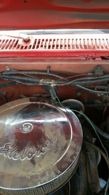
Also, I do not believe I have been messing with the proper wire. I was assuming it was the wire coming out of the connection in this pic. One of the green wires goes to the air conditioning unit, the other one is the one I thought went to coolant sensor. Now I am not too sure because my 1983 truck has those same connectors. It has the AC hooked up just like the 1982 truck but the other half in the pic is missing the whole wire. It is just unplugged and missing, however the coolant sensor is hooked up and the gauge works in that truck. I am just having a little trouble tracing the wire from the sensor to wherever it goes. Truck is tall, I am short.
 

Attachments

  • Wire Plugin.jpg
    Wire Plugin.jpg
    99 KB · Views: 129

chengny

Full Access Member
Joined
Feb 22, 2012
Posts
4,086
Reaction score
1,008
Location
NH
First Name
Jerry
Truck Year
1986
Truck Model
K3500
Engine Size
350/5.7
Neither of the two leads coming out of that double wire connector shown in the picture (laying up against the air cleaner cover) has anything to do with the coolant temperature gauge.

There should be a light green (it just happens to be the same color as the coolant sender lead) and a dark green.

The dark green is just the power to the compressor clutch and is energized by the low side pressure switch according to cooling load.

The other - light green - wire is the power to the throttle solenoid.

If the HVAC system control panel is set to any position that might possibly cause the A/C compressor to kick in, power is supplied to the throttle solenoid via the light green wire. When energized, the throttle solenoid overrides the idle speed screw to prevent a drop in engine RPM due to the additional load produced by the compressor.

Your throttle solenoid may - or may not - still be installed. If it isn't there, and you have no problem with idle speed when the A/C is running - forget about it. Cut the wire to avoid confusion.

If there is a throttle solenoid - and it still works - I suppose you could hook the light green wire up. But again, if you haven't noticed any idle bog down when the compressor clutch pulls in - you could eliminate the light green wire.


A good way to find the green wire that goes to the coolant sensor is to trace the pink wire that goes to the ignition coil back to the harness. The coolant sensing wire usually pops out of the harness loom in the same place as the coil wire.

I tried to show it here. The yellow tracer is following the coolant sensor wire:


You must be registered for see images attach
 
Last edited:

PrairieDrifter

Full Access Member
Joined
Dec 28, 2014
Posts
3,478
Reaction score
4,605
Location
North Dakota
First Name
Mason
Truck Year
84,79,77,70,48
Truck Model
Suburban k10, bonanza k10, c30 C&C, c10, gmc 1/2ton
Engine Size
350, 350, 350, 350, 350
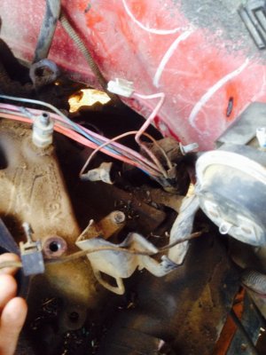
My suburban is an 84 has a/c, the wires for the a/c have a green wire going to the connector and a ground wire that grounded on the intake from the connector and it also had a wire with a clip that went to the carb I think it's black.

My temp wire comes out of the main harness with the starter and alternator wires right behind the block but it's not on the firewall, I can't tell what color the wire is its all greased up and weathered but the end of it I can tell its green and it has the spade connector not the peg style.
 

Attachments

  • image.jpg
    image.jpg
    92.9 KB · Views: 150

Splandman

Full Access Member
Joined
Jan 1, 2014
Posts
265
Reaction score
59
Location
Crescent, OK
First Name
Scott
Truck Year
1982
Truck Model
K10
Engine Size
383
Neither of the two leads coming out of that double wire connector shown in the picture (laying up against the air cleaner cover) has anything to do with the coolant temperature gauge.

There should be a light green (it just happens to be the same color as the coolant sender lead) and a dark green.

The dark green is just the power to the compressor clutch and is energized by the low side pressure switch according to cooling load.

The other - light green - wire is the power to the throttle solenoid.

If the HVAC system control panel is set to any position that might possibly cause the A/C compressor to kick in, power is supplied to the throttle solenoid via the light green wire. When energized, the throttle solenoid overrides the idle speed screw to prevent a drop in engine RPM due to the additional load produced by the compressor.

Well this may explain why nothing that I have attempted has made my gauge work. It also means that neither of the trucks have the throttle solenoid hooked up.

My wife will find this highly entertaining as I have spent quite some time screwing with this wire.
 

Latest posts

Forum statistics

Threads
42,207
Posts
911,357
Members
33,708
Latest member
btrain04
Top