What is this box on the diagram?

Disclaimer: Links on this page pointing to Amazon, eBay and other sites may include affiliate code. If you click them and make a purchase, we may earn a small commission.

R8rPhan

Full Access Member
Joined
Feb 5, 2017
Posts
452
Reaction score
42
Location
California
First Name
Mark
Truck Year
1973 (1979?)
Truck Model
C10 long bed (Frankenstein truck)
Engine Size
307
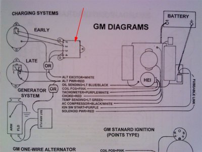
EZ Wire instructions show three types of charging systems..

late model alternator, early model alternator, and generator...

Mine had three wires going to it.. two that used a modular plug that plugged directly into the top of the alternator, and one heavy one (I assume is the output) that connects to a stud on the back of the alternator...

But I don't have this 'box' they are showing (red arrow is pointing to it in the image below).. What is it? Is it just the fusible link/terminal block? Or is it supposed to be some sort of regulator or whatever?..

attachment.php


Whatever it is, I don't think I have one, so I'm not sure how to wire this system... The existing system, had the two small wires that ran into the general engine bay harness, and one thick red one that went to the fusible link/terminal block..

In the following image, the two red wires and one dark wire going down towards the bottom of the picture are the ones that went to the alternator...

attachment.php
 

Attachments

  • C10-charging-diagram-01.jpg
    C10-charging-diagram-01.jpg
    74.9 KB · Views: 6,661

350runner

Full Access Member
Joined
Feb 9, 2013
Posts
2,858
Reaction score
224
Location
tx
First Name
Ceasar
Truck Year
82
Truck Model
c10
Engine Size
350
Looks too be the old 70s voltage regulator.

Sent from my LGLS991 using Tapatalk
 

R8rPhan

Full Access Member
Joined
Feb 5, 2017
Posts
452
Reaction score
42
Location
California
First Name
Mark
Truck Year
1973 (1979?)
Truck Model
C10 long bed (Frankenstein truck)
Engine Size
307
Looks too be the old 70s voltage regulator.

Sent from my LGLS991 using Tapatalk

So now I'm confused... lol

The 'late model' diagram shows one of the wires on the modular plug going to the terminal where the big red output wire attaches..


Does that sound like the way things should work?

If so, why didn't they do that on the original?

Thanks,
Mark
:cheers:
 

75gmck25

Full Access Member
Joined
Oct 13, 2016
Posts
2,038
Reaction score
1,838
Location
Northern Virginia
First Name
Bruce
Truck Year
1975
Truck Model
K25 Camper Special TH350 NP203
Engine Size
5.7
That box is an external voltage regulator for the older alternators. Chevy used all internally regulated alternators on the square body, so your truck does not have the external box.

The wiring for the 10si (or 12si) alternator should have three wires:
- Large wire, (probably 10 gauge) connected to the large BAT terminal on the alternator.
The original routing usually had this wire running back along the passenger side valve cover, then through a protective metal tube on the back side of the engine (keeps it away from exhaust heat), and then down to the large post on the starter. The large wire from the battery positive is also connected to that post, so its really just connecting the alternator to the battery.
Simpler routing - run the 10 gauge wire directly from the alternator bat terminal over to the positive battery terminal, using a 14 gauge fusible link to protect it. Its probably a 63 amp alternator, so you could also use a 60 amp fuse instead of the fusible link.

- The two wire plug on the back (terminal numbers should be on the case)
#1 wire - Dash light. This runs back to an ignition-switched 12 volt source, usually through the alt bulb (or a resistor) in the dash. 12 volts on this wire is what make the alternator start charging. It must be switched by the ignition, not on all the time.

#2 wire - Voltage sense wire. Stock wiring runs back into the wiring harness where it can sense voltage closer to the fuse box. However, many folks just jump that wire right over to the large bat terminal. The only downside of using the bat terminal is that it is measuring voltage at the alternator and not really sensing the full voltage drop from load.

Hope this info helps. Its really a very simple wiring scheme.

Bruce
 

MikeB

Full Access Member
Joined
Apr 4, 2014
Posts
1,749
Reaction score
937
Location
North Texas
First Name
Mike
Truck Year
1969
Truck Model
C10
Engine Size
355
#2 wire - Voltage sense wire. Stock wiring runs back into the wiring harness where it can sense voltage closer to the fuse box. However, many folks just jump that wire right over to the large bat terminal. The only downside of using the bat terminal is that it is measuring voltage at the alternator and not really sensing the full voltage drop from load.

That's a good explanation of why it's best not to tie the alternator sense terminal to the BAT terminal.

Usually it's not much of an issue, but under a heavy electrical load, the alternator could think, "Hey my sense terminal says we've got 14.2 volts, so I can relax a little." But the fuse panel may be getting only 13 volts. This is especially true when loading down an older wiring system that uses smaller gauge wires. Also, terminal corrosion and accessories--and even an HEI--can drop voltage at the fuse panel. If you've ever installed a modern harness like one from AAW, you'll see they use 8ga wires between starter and alternator, and maybe even feed the fuse panel with an 8ga wire.

On my 82 C10, the alternator output goes directly to the BAT terminal on the starter, and then the sense terminal is connected to a terminal block on the firewall. So, the alternator tries to output enough current to keep the terminal block at 14.2 volts.

On another note, I suggest the OP find a wiring diagram for a 73 truck. It will show wire colors and gauge (size). Also, I'd replace the yellow crimp connectors with soldered connectors. These heat shrink solder connectors work great, but are expensive. You can also just remove the yellow plastic from a standard butt connector and solder the wires in each end of the metal tube, then protect with heat shrink.

Heat shrink solder connectors: https://www.delcity.net/store/Heat-Shrink,-Solder-&-Crimp-Butt-Connectors/p_805407.h_801820
 
Last edited:

Forum statistics

Threads
42,223
Posts
911,681
Members
33,729
Latest member
Misty Blue
Top