

WranglerTJForum
Full Access Member
- Joined
- Jul 7, 2025
- Posts
- 150
- Reaction score
- 228
- Location
- Gillette, WY
- First Name
- Chris
- Truck Year
- 1973
- Truck Model
- K10
- Engine Size
- 396
The time has come to re-wire my dual saddle fuel tanks on my 1973 K10.
I went ahead and purchased the Pollack valve from the newer (EFI model) K10s. It came with the Pollack valve, a DPDT switch, and this wiring diagram:
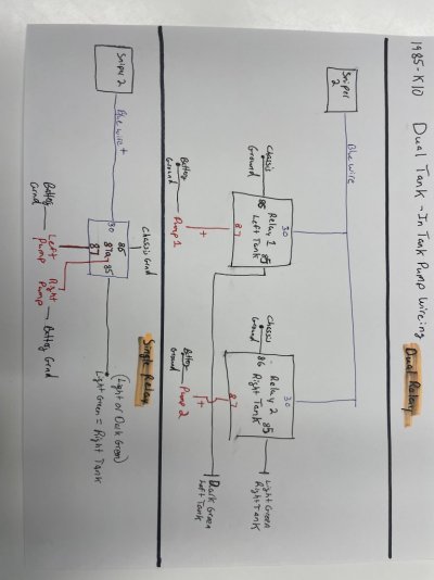
This wiring diagram makes complete sense to me. Where I am struggling now is I want to include a fuel pump relay in order to take the load of the DPDT circuit.
I'm using this relay:
As I understand it, the relay should be wired as such:
Makes perfect sense thus far.
The part where I get confused is how this relay integrates to the original wiring diagram.
In the original diagram that came with the Pollack valve, the DPDT switch has 4 wires going to it.
1) Ground
2) 12V
3) Main fuel pump
4) Auxiliary fuel pump
Do those wires going to the DPDT remain unchanged with the addition of the relay? Given that the relay now feeding the two fuel pumps directly, I would imagine that the DPDT now only has a ground and 12V wire going to it, but then that has me confused about how it's able to discern between the main pump and the auxiliary pump.
I'm sure I'm overthinking this but since I'm not an electrical guy I want to make sure I get it right the first time.
I went ahead and purchased the Pollack valve from the newer (EFI model) K10s. It came with the Pollack valve, a DPDT switch, and this wiring diagram:
You must be registered for see images attach
This wiring diagram makes complete sense to me. Where I am struggling now is I want to include a fuel pump relay in order to take the load of the DPDT circuit.
I'm using this relay:
Amazon.com: Mr. Gasket Relay Kit - Fuel Pump 30 Amp : Automotive
Buy Mr. Gasket Relay Kit - Fuel Pump 30 Amp: Fuel Pump - Amazon.com ✓ FREE DELIVERY possible on eligible purchases
www.amazon.com
As I understand it, the relay should be wired as such:
| 1. Battery +12 V → 10 A fuse → Relay Pin 30 V | |
| 2. Relay Pin 86 (coil trigger) → should get switched 12 V from the DPDT switch, not constant power. | |
| • The DPDT switch position determines whether the relay coil energizes. • That's how the relay "chooses" between 87 (Main pump) and 87a (Aux pump). | |
| 3. Relay Pin 85 → chassis ground. | |
| 4. Relay Pin 87 → Main pump positive feed. | |
| 5. Relay Pin 87a → Aux pump positive feed. | |
| 6. Both pumps ground directly to |
Makes perfect sense thus far.
The part where I get confused is how this relay integrates to the original wiring diagram.
In the original diagram that came with the Pollack valve, the DPDT switch has 4 wires going to it.
1) Ground
2) 12V
3) Main fuel pump
4) Auxiliary fuel pump
Do those wires going to the DPDT remain unchanged with the addition of the relay? Given that the relay now feeding the two fuel pumps directly, I would imagine that the DPDT now only has a ground and 12V wire going to it, but then that has me confused about how it's able to discern between the main pump and the auxiliary pump.
I'm sure I'm overthinking this but since I'm not an electrical guy I want to make sure I get it right the first time.