

You are using an out of date browser. It may not display this or other websites correctly.
You should upgrade or use an alternative browser.
You should upgrade or use an alternative browser.
The never ending 700r4 Lockup questions haha
- Thread starter usar17
- Start date
Disclaimer: Links on this page pointing to Amazon, eBay and other sites may include affiliate code. If you click them and make a purchase, we may earn a small commission.
Jims86
Full Access Member
- Joined
- Aug 3, 2010
- Posts
- 5,492
- Reaction score
- 133
- Location
- Patterson,Ca
- First Name
- Jim
- Truck Year
- 1986
- Truck Model
- K10 Suburban Silverado
- Engine Size
- 5.7 TBI
ok i just tested that solid blue is 12V with key and that cuts with the brake applied. that should go to A correct? it currently supplies power to the Vacuum Switch, EGR solenoid, and pin B on the tranny connector...
Yes. it needs to go from the brake switch to A
Lets do an experiment. take the wire from pin D, and run a wire that has a stripped end, so you can touch it to a ground while you are driving. Wire Pin A and the brake switch together.
Drive up to 35, and ground the wire ran from d, and per all the diagrams, it should lock up. If that is successful, we will check the wire from B with a test light.
usar17
Full Access Member
- Joined
- May 3, 2012
- Posts
- 596
- Reaction score
- 17
- Location
- PA
- First Name
- Shawn
- Truck Year
- 1985/87
- Truck Model
- K20 Silverado
- Engine Size
- TBI350/700r4/NP208
Ok so I cut out the vacuum switch and wired the lines together. I'm getting 12v till i press the brakes on both pins A and B. That right or wrong?
usar17
Full Access Member
- Joined
- May 3, 2012
- Posts
- 596
- Reaction score
- 17
- Location
- PA
- First Name
- Shawn
- Truck Year
- 1985/87
- Truck Model
- K20 Silverado
- Engine Size
- TBI350/700r4/NP208
If i cut B and run that wire to the ECM with D I should be good correct? so long as A still functions when i cut B.
I'm assuming the ECM locks up the transmission by grounding D. What is the function of B then?
I'm assuming the ECM locks up the transmission by grounding D. What is the function of B then?
Jims86
Full Access Member
- Joined
- Aug 3, 2010
- Posts
- 5,492
- Reaction score
- 133
- Location
- Patterson,Ca
- First Name
- Jim
- Truck Year
- 1986
- Truck Model
- K10 Suburban Silverado
- Engine Size
- 5.7 TBI
Ok so I cut out the vacuum switch and wired the lines together. I'm getting 12v till i press the brakes on both pins A and B. That right or wrong?
Ok, we are going to need to stop until I can see exactly what we are dealing with in that trans. Pin B is supposed to be the high gear signal, but I dont know what it is in tha case of this trans.where was D going on the old setup?
usar17
Full Access Member
- Joined
- May 3, 2012
- Posts
- 596
- Reaction score
- 17
- Location
- PA
- First Name
- Shawn
- Truck Year
- 1985/87
- Truck Model
- K20 Silverado
- Engine Size
- TBI350/700r4/NP208
D was a yellow wire that went to a connector. That connector was plugged into if i remember correctly "EGR BLEED SOL" that was inline with the vacuum line for the ERG. Found a photo of what it looked like here: http://imgur.com/onlBY
B in the old set up came up to the firewall where it split off into 3 lines: the Vacuum sensor, other side of that ERG connector, and inside the cab. Inside the cab it goes to the brake switch. This wire was 12v hot with ignition so long as the brake was not pressed.
A went straight to the fire wall. Inside it also went to that controller on the steering column. This received 12v only under the conditions of ign, no brake, and vacuum sensor circuit closed.
The other side of the vacuum sensor, blue with black stripe, also went inside to the controller on the base of the steering column.
Jims86
Full Access Member
- Joined
- Aug 3, 2010
- Posts
- 5,492
- Reaction score
- 133
- Location
- Patterson,Ca
- First Name
- Jim
- Truck Year
- 1986
- Truck Model
- K10 Suburban Silverado
- Engine Size
- 5.7 TBI
Ok, I know pin A is positive directly to the TCC solenoid.
Pin D is the Ground side of the TCC?
I dont know what B is connected to inside the trans. All the info I can find, is on the later 700r4, that had the auxilliary valve body(87^)
you can go ahead andnd see if it pocks when you touch the extension wire from D, and if it does, go ahead and wire that to A7, and see if it wil lock up at the higher gears via the ECM. Not sure if it will without the high gear signal.
usar17
Full Access Member
- Joined
- May 3, 2012
- Posts
- 596
- Reaction score
- 17
- Location
- PA
- First Name
- Shawn
- Truck Year
- 1985/87
- Truck Model
- K20 Silverado
- Engine Size
- TBI350/700r4/NP208
Im going to have to do some experimenting with this. Ive been reading over tons of websites, apparently there is about 13 different combinations of how the 700r4 was wired internally and externally. from normally open 4th gears, to normally closed, to internal ground, to external grounding.
From what i read it seems like pin A energizes the solenoid inside to lock the TCC. This then self grounds sending a ground signal through D to the EGR bleed Sol. I wasnt able to figure out much about pin B tho. It seems only some variations sent signals for when 4th gear was engaged. The fact that im getting positive current into the transmission on pins A and B worries me. I could not find anything stating why B would be charged inside the case.
I can attempt to run A hot with through the brake switch, control D as a ground, and i guess run B through a test light to look for signaling. Was that your thought process? the test light would get (+) from pin B, hopefully
usar17
Full Access Member
- Joined
- May 3, 2012
- Posts
- 596
- Reaction score
- 17
- Location
- PA
- First Name
- Shawn
- Truck Year
- 1985/87
- Truck Model
- K20 Silverado
- Engine Size
- TBI350/700r4/NP208
ok I did some experimenting today. I attempted to ground pin D to lock up the transmission. Did not work. So here is what I found after wiring up a few test lights.
Pin A: 12v with Key Ign, No Brake and Vacuum Sensor closed
Pin B: 12v with Key Ign, No Brake
Pin D: SENDS a Ground signal in 3rd and 4th gears from the tranny to the EGR bleed solenoid.
EDIT: This is the best photo i can find of how mine is wired. Unfortunitly it is blurry. IT appears that controller on my column is a 4WD relay. lol any clue how i can still swing this?
You must be registered for see images attach
Last edited:
Jims86
Full Access Member
- Joined
- Aug 3, 2010
- Posts
- 5,492
- Reaction score
- 133
- Location
- Patterson,Ca
- First Name
- Jim
- Truck Year
- 1986
- Truck Model
- K10 Suburban Silverado
- Engine Size
- 5.7 TBI
ok I did some experimenting today. I attempted to ground pin D to lock up the transmission. Did not work. So here is what I found after wiring up a few test lights.
Pin A: 12v with Key Ign, No Brake and Vacuum Sensor closed
Pin B: 12v with Key Ign, No Brake
Pin D: SENDS a Ground signal in 3rd and 4th gears from the tranny to the EGR bleed solenoid.
EDIT: This is the best photo i can find of how mine is wired. Unfortunitly it is blurry. IT appears that controller on my column is a 4WD relay. lol any clue how i can still swing this?
You must be registered for see images attach
Ok...there is the answer to the mystery. Pin D goes to C7 on the ecm, looks like they wer using high gear signals to control egr.
Pin A will go directly to the brake switch.
Pin B...heres the deal. the diagram shows the ground sid of the TCC solenoid grounding in the trans. you would have to open the pan, and run the ground wire to pin B on the inside of the plug, the the wir from B goes to A7, which will activate the ground to the solenoid, locking the converter.
Jims86
Full Access Member
- Joined
- Aug 3, 2010
- Posts
- 5,492
- Reaction score
- 133
- Location
- Patterson,Ca
- First Name
- Jim
- Truck Year
- 1986
- Truck Model
- K10 Suburban Silverado
- Engine Size
- 5.7 TBI
you can apply voltage but you wont see anything, you may hear it.Can I test the solenoid while I'm in there? Run 12v to it and see if it moves?
And will this mess with my 4wd at all?
No, it shouldnt mess with 4wd, i dont understand the 4wd rely, unless it was meant to keep from locking up while wheelin.
usar17
Full Access Member
- Joined
- May 3, 2012
- Posts
- 596
- Reaction score
- 17
- Location
- PA
- First Name
- Shawn
- Truck Year
- 1985/87
- Truck Model
- K20 Silverado
- Engine Size
- TBI350/700r4/NP208
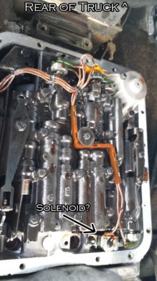
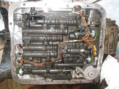
ok I got the pan dropped and the filter out of the way. I'm now in unfamiliar territory. I see 4 pressure sensors and what I'm assuming is the Lock-Up solenoid. Wires all over the place and they all seem to tie together somehow. The solenoid only has one wire on it. I'm gonna search the web awhile trying to identify everything. I wanted to get this up in here in the mean time incase you are free to tell me what to do now. Attached is a photo of mine and one I found on the web very similar that is clearer. Mine is the one with the labels
Attachments
usar17
Full Access Member
- Joined
- May 3, 2012
- Posts
- 596
- Reaction score
- 17
- Location
- PA
- First Name
- Shawn
- Truck Year
- 1985/87
- Truck Model
- K20 Silverado
- Engine Size
- TBI350/700r4/NP208
ok that is the solenoid. I don't know what the pressure switch next to it is for but it runs to one terminal on the 4th gear switch at the back then from the 4th gear to Pin D.
Pin B I think goes to the switch in the middle of the back. im very confused trying to trace these wire still zip tied with fluid dripping on me haha
EDIT: Ok found this. Makes a little sense. Opinions on what I should do??
Pin B I think goes to the switch in the middle of the back. im very confused trying to trace these wire still zip tied with fluid dripping on me haha
EDIT: Ok found this. Makes a little sense. Opinions on what I should do??
You must be registered for see images attach
Last edited:
Jims86
Full Access Member
- Joined
- Aug 3, 2010
- Posts
- 5,492
- Reaction score
- 133
- Location
- Patterson,Ca
- First Name
- Jim
- Truck Year
- 1986
- Truck Model
- K10 Suburban Silverado
- Engine Size
- 5.7 TBI
ok that is the solenoid. I don't know what the pressure switch next to it is for but it runs to one terminal on the 4th gear switch at the back then from the 4th gear to Pin D.
Pin B I think goes to the switch in the middle of the back. im very confused trying to trace these wire still zip tied with fluid dripping on me haha
EDIT: Ok found this. Makes a little sense. Opinions on what I should do??
You must be registered for see images attach
Ok, i do know that you will need a 2 wire later model TCC solenoid.
I hand drew this for clarity from the 90 manual, this is the circuit you will need to end up with.
You must be registered for see images attach
Maybe HR can provide a little more clarity on the old switches, and which, if any can be retained for the new circuit.
All this aside, there is the option to just install a simplified setup, using a pressure switch, mounted in the 4th gear position, operating the ground side of the TCC solenoid<<<just throwing tha out there, if it gets too complicated.