

You are using an out of date browser. It may not display this or other websites correctly.
You should upgrade or use an alternative browser.
You should upgrade or use an alternative browser.
Function testing factory Gauges.
- Thread starter Irishman999
- Start date
Disclaimer: Links on this page pointing to Amazon, eBay and other sites may include affiliate code. If you click them and make a purchase, we may earn a small commission.
- Joined
- Aug 29, 2010
- Posts
- 47,014
- Reaction score
- 9,015
- Location
- OKC, OK
- First Name
- HotRod
- Truck Year
- 85 K20 LWB
- Truck Model
- Silverado
- Engine Size
- 454 - Turbo 400 - 3.73
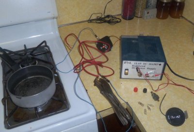
I have had 3 different gauges in the truck, 3 different Senders in the truck. Finally to quit guessing, I've take each of the 3 gauges and tested them in my other truck where the gauge works and all 3 gauges were identical to what that truck reads normally, so I know the gauges are good. The senders I tested with a known good gauge in a pan of hot boiling water on the stove and know the senders are good too. Also ohms tested the senders. All is good.


Attachments
chengny
Full Access Member
- Joined
- Feb 22, 2012
- Posts
- 4,086
- Reaction score
- 1,008
- Location
- NH
- First Name
- Jerry
- Truck Year
- 1986
- Truck Model
- K3500
- Engine Size
- 350/5.7
Have you checked the resistance across the entire control side under actual conditions? By that I mean from the gauge stab-in clip (left side looking fwd) directly to ground but via the variable resistance (i.e the sender).
With the engine up to normal temperature and key in the RUN position, pull the gauge out of the instrument panel and get an ohm value of the sensing leg.
With one test lead in the LH clip and the other securely to ground (preferably close to the sender - use an extra jumper) you should read about 250 ohms.
Note: This test is done with the sender in the coolant flow and the dark green wire still connected.
Check at various temps according to the resistance chart below:
While you're set up for that test (and before you do it), pull the clip from the sender and check the sensing leg for 3 things:
Full continuity from the gauge stab to the sender clip - should be 0 ohms
A short to ground within the sensing leg. Test leads to the sender clip (or gauge clip) and ground - resistance should be infinite. Anything less indicates a partial ground which will intensify when power is applied
Stray voltage. With the gauge pulled out and ignition in the RUN position, attach the test leads to ground and the sender clip. Fluke set to VDC. There should be no voltage available in that wire.
If these tests all turn out well - condsider yourself lucky I'd say.
The worst electrical problems to find and repair are the ones that are buried within the wiring harness.
With the engine up to normal temperature and key in the RUN position, pull the gauge out of the instrument panel and get an ohm value of the sensing leg.
With one test lead in the LH clip and the other securely to ground (preferably close to the sender - use an extra jumper) you should read about 250 ohms.
Note: This test is done with the sender in the coolant flow and the dark green wire still connected.
Check at various temps according to the resistance chart below:
You must be registered for see images attach
While you're set up for that test (and before you do it), pull the clip from the sender and check the sensing leg for 3 things:
Full continuity from the gauge stab to the sender clip - should be 0 ohms
A short to ground within the sensing leg. Test leads to the sender clip (or gauge clip) and ground - resistance should be infinite. Anything less indicates a partial ground which will intensify when power is applied
Stray voltage. With the gauge pulled out and ignition in the RUN position, attach the test leads to ground and the sender clip. Fluke set to VDC. There should be no voltage available in that wire.
If these tests all turn out well - condsider yourself lucky I'd say.
The worst electrical problems to find and repair are the ones that are buried within the wiring harness.
Last edited:
- Joined
- Aug 29, 2010
- Posts
- 47,014
- Reaction score
- 9,015
- Location
- OKC, OK
- First Name
- HotRod
- Truck Year
- 85 K20 LWB
- Truck Model
- Silverado
- Engine Size
- 454 - Turbo 400 - 3.73
No, I have not done this test at the lugs, but I've done it under the hood and all was well. Knowing for a fact, the gauge is good, I'd say this test you speak of WILL show some sort of failure.Have you checked the resistance across the entire control side under actual conditions? By that I mean from the gauge stab-in clip (left side looking fwd) directly to ground but via the variable resistance (i.e the sender).
With the engine up to normal temperature and key in the RUN position, pull the gauge out of the instrument panel and get an ohm value of the sensing leg.
With one test lead in the LH clip and the other securely to ground (preferably close to the sender - use an extra jumper) you should read about 250 ohms.
Note: This test is done with the sender in the coolant flow and the dark green wire still connected.
Check at various temps according to the resistance chart below:
You must be registered for see images attach
While you're set up for that test (and before you do it), pull the clip from the sender and check the sensing leg for 3 things:
Full continuity from the gauge stab to the sender clip - should be 0 ohms
A short to ground within the sensing leg. Test leads to the sender clip (or gauge clip) and ground - resistance should be infinite. Anything less indicates a partial ground which will intensify when power is applied
Stray voltage. With the gauge pulled out and ignition in the RUN position, attach the test leads to ground and the sender clip. Fluke set to VDC. There should be no voltage available in that wire.
If these tests all turn out well - condsider yourself lucky I'd say.
The worst electrical problems to find and repair are the ones that are buried within the wiring harness.
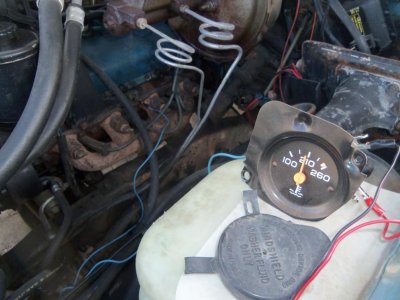
BUT, I just recalled, with 2 of those other KNOWN good gauges, I was not able to get either one to read off of the sender with jumper leads from the battery direct to the gauge, and a jumper lead direct to the sender. See how I did this test on the gauge to make sure it works? This is on my 84 C20 that has a working gauge. Notice the gauge is working fine.
Now I do the same exact test under hood of the 85 K1500 and I can't get that same gauge and another one to read. This is when I thought it was the sender, so I swapped it. Still no read. Then I did the hot boiling water test at the kitchen counter, nd all 3 of my senders work and read the same. The one that I thought was bad and in the truck, the one I bought at Adavance, and the one I bought at AZ. All 3 read good, a little over 210 when the water was boiling. Now that's using my alligator leads of KNOWN good wire. I mean hell, I just did the same thing on 84 C20 and the Gauges worked fine. Its as if the sender is not getting grounded to the block.
chengny
Full Access Member
- Joined
- Feb 22, 2012
- Posts
- 4,086
- Reaction score
- 1,008
- Location
- NH
- First Name
- Jerry
- Truck Year
- 1986
- Truck Model
- K3500
- Engine Size
- 350/5.7
Its as if the sender is not getting grounded to the block.
I can't imagine how it couldn't... how is the main engine to body grounding strap?
There are plenty of paths back to ground for engine mounted electricals - but you never know.
Also, maybe try using the coolant sender port on the other head. It's in the back of the head on that side. Sometimes the pipe size is bigger but you can use a bushing.
Usually there is enough slack in the green sender wire to allow you to run it over to that side without splicing in an extension.
I can't imagine how it couldn't... how is the main engine to body grounding strap?
You must be registered for see images attach
There are plenty of paths back to ground for engine mounted electricals - but you never know.
Also, maybe try using the coolant sender port on the other head. It's in the back of the head on that side. Sometimes the pipe size is bigger but you can use a bushing.
Usually there is enough slack in the green sender wire to allow you to run it over to that side without splicing in an extension.
Last edited:
- Joined
- Aug 29, 2010
- Posts
- 47,014
- Reaction score
- 9,015
- Location
- OKC, OK
- First Name
- HotRod
- Truck Year
- 85 K20 LWB
- Truck Model
- Silverado
- Engine Size
- 454 - Turbo 400 - 3.73
Its as if the sender is not getting grounded to the block.
I can't imagine how it couldn't... how is the main engine to body grounding strap?
You must be registered for see images attach
There are plenty of paths back to ground for engine mounted electricals - but you never know.
Also, maybe try using the coolant sender port on the other head. It's in the back of the head on that side. Sometimes the pipe size is bigger but you can use a bushing.
Usually there is enough slack in the green sender wire to allow you to run it over to that side without splicing in an extension.
I haven't found one yet at all. But, I do get continuity from the Alternator bracket and Pos Bat terminal so I'd assume it's grounded thru the negative bat cable to the Alternator bracket to intake and water pump. I plan on doing the Big 3 upgrade very soon and that for certain will take care of any grounding issues.
I would have to splice and extension because I had a bad melt on a header from before I bought the truck, so I cut it off at the burn and put a new end spade on it. So it's only got about 2 inches of slack and could barely reach the intake threaded gauge port. And I thought of doing that too. Putting the gauge sender in the intake, then my COLD/HOT Switch for the idiot lights and Electric Choke in the head.
- Joined
- Dec 7, 2010
- Posts
- 24,532
- Reaction score
- 5,826
- Location
- Southeast PA
- First Name
- Paw Paw
- Truck Year
- 2007
- Truck Model
- Chevrolet Tahoe LT
- Engine Size
- 5.3, 4WD
C'mon Hotrod, god damn!!!!! Fix this POFS!!!! 
You need to ground that head man. Continuity don't mean ****. Run a wire or cable from the ground at the alt bracket and bolt it to a boss on that head just to eliminate that.
Something else to add to the PAP list, cables and ground straps.
You need to ground that head man. Continuity don't mean ****. Run a wire or cable from the ground at the alt bracket and bolt it to a boss on that head just to eliminate that.
Something else to add to the PAP list, cables and ground straps.
Last edited:
- Joined
- Aug 29, 2010
- Posts
- 47,014
- Reaction score
- 9,015
- Location
- OKC, OK
- First Name
- HotRod
- Truck Year
- 85 K20 LWB
- Truck Model
- Silverado
- Engine Size
- 454 - Turbo 400 - 3.73
C'mon Hotrod, god damn!!!!! Fix this POFS!!!!
You need to ground that head man. Continuity don't mean ****. Run a wire or cable from the ground at the alt bracket and bolt it to a boss on that head just to eliminate that.
Something else to add to the PAP list, cables and ground straps.
I figured I'd do the Big 3 and have all that covered. I want to ground the block to the frame, and ground the block to the cab. You can trust, I'm going to do that before I BUY a printed or another Cluster.
I'm really starting to feel incompetent. After the frustration over the damn interior air distributor and now this fuggin gauge, I'm beginning to think I'm losing my magic touch and can fix any damn thing.
chengny
Full Access Member
- Joined
- Feb 22, 2012
- Posts
- 4,086
- Reaction score
- 1,008
- Location
- NH
- First Name
- Jerry
- Truck Year
- 1986
- Truck Model
- K3500
- Engine Size
- 350/5.7
You must be registered for see images attach
How about doing this same test (in the problem truck, the 85 1/2 T), but this time pull the sender out of the head.
Run a heavy jumper from the sender casing directly over to the negative battery terminal. Apply some heat to the sender using a contractors flood light, cigarettte lighter, hair dryer, whatever... and check gauge for function. If it reacts normally, disco the jumper to bat neg and re-install sender into the head. Check again for function.
This test will eliminate/confirm sender grounding path all the way from the head back to bat neg as an issue
The entire circuit will be reduced to it's most basic components and everything will be totally visible to the eye.
You know, sometimes when faced with this type of problem (one that should be a simple fix yet defies solution) - I find that it often helps to step back and let it go for a while.
Just walk away - don't even think about it for a few days. The answer may just pop into your head.
That, or another trick is to ask one of your kids or a friend to help you solve it. They don't need to be a mechanic - just a working knowledge of automotive systems.
The suggestions they provide, while often wrong or been checked many times, frequently cause you to rethink a basic troubleshooting step. One that it so simple that you (as an ace mechanic) blew right past. You know, checked it off as "not the problem" without really looking at it.
Good luck, I'm watching this now.
You must be registered for see images attach
Last edited:
- Joined
- Aug 29, 2010
- Posts
- 47,014
- Reaction score
- 9,015
- Location
- OKC, OK
- First Name
- HotRod
- Truck Year
- 85 K20 LWB
- Truck Model
- Silverado
- Engine Size
- 454 - Turbo 400 - 3.73
You must be registered for see images attach
And that is the OE gauge that originaly came out of my 85 K1500, being tested underhood on the 84 C20 with a known working gauge and sender. It reads Identical to the gauge that's in the 84 C20 cluster. So I know the gauge is good and functioning.
chengny
Full Access Member
- Joined
- Feb 22, 2012
- Posts
- 4,086
- Reaction score
- 1,008
- Location
- NH
- First Name
- Jerry
- Truck Year
- 1986
- Truck Model
- K3500
- Engine Size
- 350/5.7
Bump.
Excuse me! I wasn't finished sharing my wisdom yet.
Now I'm done. I'll just climb down from my soapbox now.
Seriously, I wasn't aware that posts were visible while still being written. I thought that nothing showed up until the "submit" button was pushed.
Excuse me! I wasn't finished sharing my wisdom yet.
Now I'm done. I'll just climb down from my soapbox now.
Seriously, I wasn't aware that posts were visible while still being written. I thought that nothing showed up until the "submit" button was pushed.
Last edited:
- Joined
- Aug 29, 2010
- Posts
- 47,014
- Reaction score
- 9,015
- Location
- OKC, OK
- First Name
- HotRod
- Truck Year
- 85 K20 LWB
- Truck Model
- Silverado
- Engine Size
- 454 - Turbo 400 - 3.73
Bump.
Excuse me! I wasn't finished sharing my wisdom yet.
Now I'm done. I'll just climb down from my soapbox now.
Seriously, I wasn't aware that posts were visible while still being written. I thought that nothing showed up until the "submit" button was pushed.
hahahahah, they're not. You must have submited the pic, then went back to edit. But now that I see what's up, I"ll go back and read that post.
- Joined
- Aug 29, 2010
- Posts
- 47,014
- Reaction score
- 9,015
- Location
- OKC, OK
- First Name
- HotRod
- Truck Year
- 85 K20 LWB
- Truck Model
- Silverado
- Engine Size
- 454 - Turbo 400 - 3.73
You must be registered for see images attach
How about doing this same test (in the problem truck, the 85 1/2 T), but this time pull the sender out of the head.
Run a heavy jumper from the sender casing directly over to the negative battery terminal. Apply some heat to the sender using a contractors flood light, cigarettte lighter, hair dryer, whatever... and check gauge for function. If it reacts normally, disco the jumper to bat neg and re-install sender into the head. Check again for function.
This test will eliminate/confirm sender grounding path all the way from the head back to bat neg as an issue
The entire circuit will be reduced to it's most basic components and everything will be totally visible to the eye.
You know, sometimes when faced with this type of problem (one that should be a simple fix yet defies solution) - I find that it often helps to step back and let it go for a while.
Just walk away - don't even think about it for a few days. The answer may just pop into your head.
That, or another trick is to ask one of your kids or a friend to help you solve it. They don't need to be a mechanic - just a working knowledge of automotive systems.
The suggestions they provide, while often wrong or been checked many times, frequently cause you to rethink a basic troubleshooting step. One that it so simple that you (as an ace mechanic) blew right past. You know, checked it off as "not the problem" without really looking at it.
Good luck, I'm watching this now.
You must be registered for see images attach
I did do the same test on the problem truck. NO Reading. And I did do the sender out of the head test over the battery jumperes and a cig lighter. Didn't seem to get results so I figured the sender needed to be submerged in water, so I took the test into the house with a DC power supply as the battery, and as soon as the water came to a rolling boil submerged it and the qauge when right over 210, probably more like 220 degrees.
Yes, you're right and why I've left alone and going to do the Big 3 then see if it works cuz it appears to me it's not getting grounded to the block for some reason. But, I did run a 10gu wire clamped the hex of the sender with vise grips then clamped it to the negative battery terminal which should have grounded the sender and that also did not work after reinstalling the sender knowing it was good. I've tested 3 gauges, and 3 senders which all tested good and used all combos and none work in the truck. I'm down to it being, block not grounded to the chassis, or defective printed circuit. Really leaning more toward block not gounded but my oil gauge works fine.
- Joined
- Dec 7, 2010
- Posts
- 24,532
- Reaction score
- 5,826
- Location
- Southeast PA
- First Name
- Paw Paw
- Truck Year
- 2007
- Truck Model
- Chevrolet Tahoe LT
- Engine Size
- 5.3, 4WD
Maybe there is air trapped in the head. 
Posted from mobile...
Posted from mobile...
- Joined
- Aug 29, 2010
- Posts
- 47,014
- Reaction score
- 9,015
- Location
- OKC, OK
- First Name
- HotRod
- Truck Year
- 85 K20 LWB
- Truck Model
- Silverado
- Engine Size
- 454 - Turbo 400 - 3.73
Maybe there is air trapped in the head.
Posted from mobile...
Don't think so cuz when I pulled the sender coolant spewed out. Not much though cuz I has sucked it all out thru the radiator. Only lost like 2 tablespoons of coolant using the Transfer pump.
 But I did consider that, so I drove the truck to get it good and hot, verified thermostat popped and let all the cooling system burp to no avail. I'm realy leaning toward the ground being the issue. It just doen't make sense the oil pressure gauge works and it's also grounded to the block. I've even considered putting my Temp Sender in the Aluminum Intake port, and moving my 2 prong Hot/Cold Idiot Light switch to the head. Reasons being, the head will read hotter first with exhaust gasses right there at the port. The second that motor hits 253 degrees, it sets the light off. If the switch is in the intake and waits for the intake coolant to get to 253 degrees, the head temp could be 265-270 by then. That's to fuggin hot and will crack those 882 Crate motor heads almost for certain.
 This is why I tell people, when a RED light comes on for Oil Pressure or Temp and it's staying on, shut it down NOW. Don't try to make it that extra mile and you'd be home. Unless you're in a dangerous place, don't even try it. Just shut it down. That extra mile you wanted to get could be the difference of needing a new motor or a set of heads etc. This is also why I like lights too. Sometimes I get on long drives and my head starts thinking about ****, I may be not be paying attention to the gauges, and I'd notice a light come on then check the gauge and decide what I needed to do. But, even in deep thought on a long drive. I'm probably checking the gauges sub consiously. I've always been a gauge freak. I like to know what ***** doing constantly.
Similar threads
- Replies
- 8
- Views
- 703
- Replies
- 15
- Views
- 875
- Replies
- 5
- Views
- 927
- Replies
- 5
- Views
- 393