ac control vacume line source

Disclaimer: Links on this page pointing to Amazon, eBay and other sites may include affiliate code. If you click them and make a purchase, we may earn a small commission.

tpjb57

Junior Member
Joined
Oct 19, 2023
Posts
2
Reaction score
0
Location
satsuma, alabama
First Name
tom
Truck Year
1989
Truck Model
blazer
Engine Size
5.7
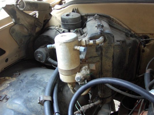
have a 89 k5 and the ac controller vacuum line is noy connected under the hood.
looked everywhere and there is no available empty line.
the round ball line goes to the cruise controller which the blazer does not have then it tees to the mass air sensor.
I'm missing something.
looked at all the diagrams.

thanks
 

Craig 85

Full Access Member
Joined
Jan 25, 2017
Posts
3,892
Reaction score
4,039
Location
Nashville, TN
First Name
Craig
Truck Year
1985
Truck Model
K30 SRW
Engine Size
454/TH-400/NP205
I think this is the vacuum line diagram for your truck.

You must be registered for see images attach
 

mibars

Full Access Member
Joined
May 13, 2023
Posts
211
Reaction score
368
Location
Nadarzyn, Poland
First Name
Michal
Truck Year
1990
Truck Model
Suburban V1500
Engine Size
350 TBI
The diagram should be right for 89 Blazer, ignoring the vacuum modulator for TH400.

MAP sensor, etc. should have separate vacuum sources, in form of two tubes going out of throttle body. Vacuum for HVAC and cruise (and transmission) comes out of the separate fitting towards the rear of the intake, not far away from distributor.
 

tpjb57

Junior Member
Joined
Oct 19, 2023
Posts
2
Reaction score
0
Location
satsuma, alabama
First Name
tom
Truck Year
1989
Truck Model
blazer
Engine Size
5.7
there is a line from the evrv solonoid to the t then cruise control servo then to the ball
I do not have cruise on the vehicle
the third port on the throttle body front has no suction
i can use a brake bleeder to create vacume on the supply line at the dash and all the servos work
so wht did the original line tie into?
 

75gmck25

Full Access Member
Joined
Oct 13, 2016
Posts
2,038
Reaction score
1,833
Location
Northern Virginia
First Name
Bruce
Truck Year
1975
Truck Model
K25 Camper Special TH350 NP203
Engine Size
5.7
This is the picture of my ‘75. The larger vacuum line coming out of the bottom of the reservoir/ball runs over to a manifold vacuum tree on the intake. You can also see the small vacuum line that runs across the plenum, and through the firewall to the dash controls. Your vacuum ball might be shaped differently, but it’s the same general design.
 

Attachments

  • PDRM0145.jpeg
    PDRM0145.jpeg
    140.3 KB · Views: 27

84GMCSierra

Full Access Member
Joined
Feb 26, 2023
Posts
302
Reaction score
355
Location
Central Arizona
First Name
Paul
Truck Year
1984
Truck Model
C2500
Engine Size
350
Sorry to jump in here, but is there a diagram like the one above for an 84 Sierra, base model, 350/TH400 with AC? Or is this diagram pretty much the same for all models with the exception of trans type?
 

75gmck25

Full Access Member
Joined
Oct 13, 2016
Posts
2,038
Reaction score
1,833
Location
Northern Virginia
First Name
Bruce
Truck Year
1975
Truck Model
K25 Camper Special TH350 NP203
Engine Size
5.7
I believe all with A/C have the same basic design, although the vacuum ball may be shaped a little different, and I’ve seen one mounted so the vacuum connections go sideways toward the drivers side.

All that canister does is provide a reservoir for vacuum, so when you accelerate and engine vacuum drops, the A/C controls still work properly.
 
Top