Steering gear input shaft leak...

Disclaimer: Links on this page pointing to Amazon, eBay and other sites may include affiliate code. If you click them and make a purchase, we may earn a small commission.

Powder96ss

Junior Member
Joined
Jul 7, 2013
Posts
24
Reaction score
6
Location
CoCo county
First Name
Ed
Truck Year
74
Truck Model
C10
Engine Size
307
I tried doing searches and came up with mixed results. As the title says, my input shaft seal is leaking, pretty damn good too. I know the seal is around $10 dollars but, from what I've gathered, the only reason it would leak is the shaft is worn, or internal damage. With that being said, is there anyone that has done the seal and had good results for the long haul or, should I just save for a new steering gear and call it good? I'm just going to replace the seal for now and see where that takes me, I'm just curious to know I guess, what others have experienced. Also, it seems everyone takes the gear box off to do this as well, can it not be done with it on?
 

89Suburban

Supporting Member
Supporting Member
Joined
Dec 7, 2010
Posts
24,532
Reaction score
5,826
Location
Southeast PA
First Name
Paw Paw
Truck Year
2007
Truck Model
Chevrolet Tahoe LT
Engine Size
5.3, 4WD
I thought Irishman99 did a steering box rebuild but I can not find it at the moment....
 

Powder96ss

Junior Member
Joined
Jul 7, 2013
Posts
24
Reaction score
6
Location
CoCo county
First Name
Ed
Truck Year
74
Truck Model
C10
Engine Size
307

chengny

Full Access Member
Joined
Feb 22, 2012
Posts
4,086
Reaction score
1,008
Location
NH
First Name
Jerry
Truck Year
1986
Truck Model
K3500
Engine Size
350/5.7
Power steering or manual? Saginaw 605 or 808?

An image would be best.

I have the rebuild procdures if you can supply the model.
 

Powder96ss

Junior Member
Joined
Jul 7, 2013
Posts
24
Reaction score
6
Location
CoCo county
First Name
Ed
Truck Year
74
Truck Model
C10
Engine Size
307
Hmmm, I believe it's an 800 since it has the 4 bolts on top of the gear box, opposite of the pitman arm shaft. If I'm not mistaken, I have to break loose the steering shaft, undo the the lock ring, use a spanner wrench to remove the first deal, replace the o-ring, then reassemble, no?
 

89Suburban

Supporting Member
Supporting Member
Joined
Dec 7, 2010
Posts
24,532
Reaction score
5,826
Location
Southeast PA
First Name
Paw Paw
Truck Year
2007
Truck Model
Chevrolet Tahoe LT
Engine Size
5.3, 4WD
Power steering or manual? Saginaw 605 or 808?

An image would be best.

I have the rebuild procedures if you can supply the model.

Can I get those off you?
 

chengny

Full Access Member
Joined
Feb 22, 2012
Posts
4,086
Reaction score
1,008
Location
NH
First Name
Jerry
Truck Year
1986
Truck Model
K3500
Engine Size
350/5.7
Saginaw Manual Steering Gear Rebuild

You must be registered for see images attach


DISASSEMBLY


1.Referring to Fig. 5, loosen adjusting screw lock nut and remove housing side cover by removing adjusting screw.
2.Loosen lock nut and back off worm bearing adjuster several turns, then remove housing end cover and gasket.
3.Remove lower thrust bearing, steering shaft and upper bearing from housing.
4.Remove ball return guide clamps and guides from ball nut. Turn ball nut over and remove ball nut from steering shaft worm.
INSPECTION OF COMPONENTS


1.Clean and inspect all ball and roller bearings and races, including race in housing.
2.Inspect pitman shaft bushings in gear housing and end cover. If bushings are worn excessively, replace bushings.
3.It is advisable to replace pitman shaft grease seal in housing to avoid possible leakage of lubricant. Seal must be installed with feather edge toward inside of housing.
4.Inspect pitman shaft for wear or pits in bearing races, which would require replacement of shaft.
5.Check shaft for straightness.
6.Inspect teeth of ball nut and pitman shaft. If scored or excessively worn it is advisable to replace both parts to insure proper mating of teeth.
7.Check serrations of pitman shaft; if twisted replace shaft.
8.Check fit of pitman shaft adjusting screw and shim in slot in end of pitman shaft. With shim in place, screw head must be free to turn in slot with zero to .002 inch end play. If end play is excessive, selectively fit a new shim, which are available in four different thicknesses.
ASSEMBLY
Lubricate all seals, bushings, bearings and gears with multi-purpose gear lube prior to installation.


1.Position ball nut over worm shaft so that deep side of teeth will be toward side cover when installed in gear housing.
2.Install exactly 1/2 the number of balls in each circuit, rocking worm shaft slightly to aid in installing balls.
3.Place about six balls in each return guide, using grease to hold balls in place.
4.Install return guides, clamp and screw.
5.Rotate worm through its complete travel several times to be sure balls are installed correctly and rotate freely.
6.Place upper bearing on worm shaft and slide worm shaft assembly into housing.
7.Place lower bearing in worm bearing adjuster and install bearing retainer.
8.Install adjuster assembly and lock nut in housing. Tighten adjuster only enough to hold worm bearings in place. Final adjustment will be made later.
9.Turn worm shaft until center groove in ball nut lines up with center of pitman shaft bushing.
10.Install pitman shaft and lash adjuster with shim so that center tooth meshes with center groove in ball nut.
11.Install side cover with gasket on lash adjuster by turning adjuster counterclockwise.
12.Install side cover bolts and washers.
13.Turn lash adjuster so that teeth on shaft and ball nut engage but do not bind.
14.Install lash adjuster lock nut loosely.
15.To protect pitman shaft seal from damage, cover shaft splines with masking tape. Slide new seal into place and seat it against shoulder in housing.
16.Install new worm shaft seal flush with surface of housing.
17.Fill gear housing with multi-purpose lubricant and adjust gear assembly as outlined previously.
 

Attachments

  • sag man rebuild.jpg
    sag man rebuild.jpg
    90.6 KB · Views: 2,164

chengny

Full Access Member
Joined
Feb 22, 2012
Posts
4,086
Reaction score
1,008
Location
NH
First Name
Jerry
Truck Year
1986
Truck Model
K3500
Engine Size
350/5.7
Saginaw 800 -808 Power Steering Gear

Overall view and adjuster plug seal assembly:

Refer to Fig. 3 and lubricate all parts as they are assembled.


1.Screw lash adjuster through side cover until cover bottoms on pitman shaft gear. Install lash adjuster lock nut while holding lash adjuster with 7/32 inch Allen wrench.
2.Mount adjuster plug in vise with soft jaws.
3.If it has been removed, assemble needle bearing by pressing towards thrust bearing end of adjuster plug against identification end of bearing. End of bearing to be flush with bottom surface of stub shaft seal bore.
4.Install stub shaft far enough to provide clearance for dust seal and retaining ring. Install new dust seal with rubber surface outward. Install new retaining ring.
5.Assemble large thrust bearing race, thrust bearing, small race and spacer (with grooves up) on adjuster plug, Fig. 17, and secure with retainer.
 

Attachments

  • 800 ex view.jpg
    800 ex view.jpg
    22.2 KB · Views: 796
  • 800 adjuster plug.jpg
    800 adjuster plug.jpg
    23.3 KB · Views: 3,086

chengny

Full Access Member
Joined
Feb 22, 2012
Posts
4,086
Reaction score
1,008
Location
NH
First Name
Jerry
Truck Year
1986
Truck Model
K3500
Engine Size
350/5.7
Disassemble 800 -808

For these steps, refer to the 3 images at the bottom of the post. They are figures 5,6 & 7 from top down:


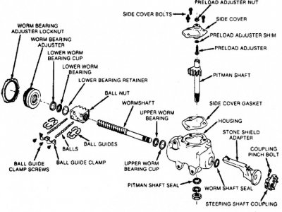
1.Referring to Fig. 3, position gear in vise with gear housing end plug facing up.
2.Rotate gear housing end plug retaining ring so that one end of ring is over hole in housing. Spring one end of ring with a punch to allow screwdriver to be inserted to lift ring out, Fig. 5.
3.Rotate coupling flange counterclockwise until rack-piston just forces end plug out of housing. Remove plug from housing. Do not rotate any further than necessary or balls fall out of their circuit and pitman shaft teeth and rack-piston will become disengaged.
4.Remove rack-piston end plug, using a 1/2 inch square drive. To make removal easier, tap rack-piston end plug with a plastic mallet to unseat threads. This is important as end plug is tightened to 75---80 ft-lbs during assembly and could break during removal if not handled carefully.
5.Remove lock nut from pitman shaft adjuster screw and discard.
6.Remove four side cover retaining screws and washers from cover.
7.Rotate pitman shaft adjuster screw with an Allen wrench until side cover is lifted free of housing.
8.Separate side cover from pitman shaft; discard side cover O-ring seal.
9.Turn coupling flange until pitman shaft teeth are centered in housing.
10.Tap end of pitman shaft with a soft mallet and slide pitman shaft out of housing.
11.Remove housing end plug O-ring seal and discard.
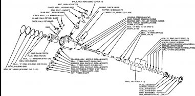
12.Insert Rack-Piston Arbor into rack-piston against end of worm, Fig. 6. Turn coupling flange counterclockwise, while holding tool tightly against worm, to force rack-piston onto arbor, and remove rack-piston from gear housing.
13.Remove stub shaft-to-coupling flange retaining screw and remove flange.
14.Remove adjuster plug lock nut by breaking it loose with hammer and punch, and remove lock nut from housing.
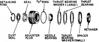
15.Loosen adjuster plug and remove from housing, Fig. 7.
16.Remove valve assembly by grasping stub shaft and pulling out.
17.Remove worm, lower thrust bearing and races from upper end of housing.


Disassemble Housing

1.Remove pitman, shaft outer dust seal retaining ring.
2.Remove outer dust seal.
3.Remove seal (double lip) by inserting offset screwdriver between seal and back-up washer and prying out of housing.
4.Remove back-up washer.
5.Remove seal (single lip) by cutting and collapsing seal.
6.Remove pitman shaft needle bearings (if necessary) with a suitable driver.
7.If connectors are to be removed, tap threads in holes of connectors using 5/16-18 NF tap. Remove connectors by using threaded bolt into tapped holes with washer and nut as extractor.

You must be registered for see images attach


Replacing Valve Spool Dampener O-Ring - refer to image above:

The rotary valve assembly includes the valve body, valve spool and stub shaft assembly. All these parts are precision units and are hydraulically balanced at the factory. Under no circumstances are parts in this unit to be replaced or interchanged with other parts or units. If unit parts are scored or damaged the entire rotary valve assembly is to be replaced. The O-ring should be replaced only if the gear squawks.


1.To replace the valve spool dampener O-ring, work spool spring into bearing diameter of stub shaft and remove spool spring.
2.Tap end of stub shaft gently against workbench to remove valve spool. The diametrical clearance between the valve body and spool may be as low as .0004 inch. The slightest cocking of the spool may jam it in the valve body.
3.Remove valve spool dampener O-ring.
4.Install new O-ring in valve spool groove, then lubricate seal in automatic transmission fluid. Do not allow seal to twist in groove.
5.With notch end of spool towards valve body, install spool, aligning spool notch with pin in stub shaft, Fig. 8.
6.Because of the small clearance between spool and valve body, extreme care must be taken when assembling these parts. Push spool evenly and slowly with a slight oscillating motion until spool reaches drive pin. Before pushing spool completely in, make sure dampener O-ring seal is evenly distributed in spool groove. Slowly push spool completely in, with extreme care taken not to cut or pinch O-ring seal.
7.Slide spool spring over stub shaft and work spring into position.
 

Attachments

  • dis 808.gif
    dis 808.gif
    14.3 KB · Views: 557
  • dis 808 b.gif
    dis 808 b.gif
    9.5 KB · Views: 489
  • dis 808 c.gif
    dis 808 c.gif
    10.2 KB · Views: 464
Last edited:

chengny

Full Access Member
Joined
Feb 22, 2012
Posts
4,086
Reaction score
1,008
Location
NH
First Name
Jerry
Truck Year
1986
Truck Model
K3500
Engine Size
350/5.7
I have a lot more on the various sub-assemblies. Will post as needed.

For example:

Assemble Rack-Piston & Worm:


1.Lubricate and install new ring back-up seal and Teflon piston ring on rack-piston nut, being careful ring and seal do not twist during installation.
2.Insert worm into rack-piston nut to bearing shoulder.
3.Align ball return guide holes with worm groove. Load balls into guide hole nearest the teflon piston ring while slowly rotating worm to left, feeding balls through circuit, Fig. 19. If balls are installed properly, the worm should turn out of the rack-piston nut.
4.Fill one-half of ball return guide with remaining balls. Place other guide over balls and plug each end with heavy grease to prevent balls from falling out when installing guides into rack-piston nut.
5.Insert guides into guide holes of rack-piston nut. Make sure black ball in guide is installed next to white ball in rack piston. Guides should fit loosely.
 

Attachments

  • loading rack & pinion.gif
    loading rack & pinion.gif
    11.4 KB · Views: 336

Powder96ss

Junior Member
Joined
Jul 7, 2013
Posts
24
Reaction score
6
Location
CoCo county
First Name
Ed
Truck Year
74
Truck Model
C10
Engine Size
307
Thanks for the info!

I just fixed my leak. I only had to change the o-ring, seal and dust cover on my adjuster plug. So far no leaks. This CAN be done without removal of the gear box, however, I removed mine because I wanted to see everything that was going on inside the gear box. What an adventure this was today! Like to hear it, here it go..............just one part though ;)

I happened to completely strip all the threads from the pitnam arm nut putting the arm back on, I had a full nut on there while I was tightening, hitting the arm with a beater, then tightening, etc. I happened to CRANK on it and BAM, it got really loose........uh oh. Backed it off and the threads were destroyed! Pulled the remaining slivers out like it was a helicoil. I thought....awwwwe ***, the threads on the pitman arm are fukced too.......nope, not one.......swEET! Luckily, the local ace had a nut that would work, it's double the thickness of the original but, it'll work. The nut is a 7/8"-14 btw, for anyone else that has retard strength too.

What a bitch the pitman arm is getting back on though. This was my first time doing this and was wingin everything hahaha but damn, if there is an easier way to put the arm on, let me know LOL. My floorjack busted a while ago, so I was doing this off my back.......I'm not exactly a little guy either haha.


Btw, I couldn't find an adjustable spanner wrench locally, so I made my own out of some 7018 I had laying around. I'm trying to post a pic of it, because its THAT cool :D but it won't let me for some reason.....idk
 
Last edited:

HotRodPC

Administrator
Staff member
Admin
Joined
Aug 29, 2010
Posts
47,014
Reaction score
9,015
Location
OKC, OK
First Name
HotRod
Truck Year
85 K20 LWB
Truck Model
Silverado
Engine Size
454 - Turbo 400 - 3.73
That's a nice build link from the Jip Forum. :waytogo:

And Chegny comes thru again as usual !!! Reps given.. AGAIN !!! :waytogo:
 

chengny

Full Access Member
Joined
Feb 22, 2012
Posts
4,086
Reaction score
1,008
Location
NH
First Name
Jerry
Truck Year
1986
Truck Model
K3500
Engine Size
350/5.7
I believe that there is a nominal fee required for Junior Members to post images ($25 check or money order - payable in advance to Mr. 89Suburban).


The real answer:

How do I attach a file to a post?

To attach a file to your post, you need to be using the main 'New Post' or 'New Thread' page and not 'Quick Reply'. To use the main 'New Post' page, click the 'Post Reply' button in the relevant thread.

On this page, below the message box, you will find a button labelled 'Manage Attachments'. Clicking this button will open a new window for uploading attachments. You can upload an attachment either from your computer or from another URL by using the appropriate box on this page. Alternatively you can click the Attachment Icon to open this page.

To upload a file from your computer, click the 'Browse' button and locate the file. To upload a file from another URL, enter the full URL for the file in the second box on this page. Once you have completed one of the boxes, click 'Upload'.

Once the upload is completed the file name will appear below the input boxes in this window. You can then close the window to return to the new post screen.

What files types can I use? How large can attachments be?

In the attachment window you will find a list of the allowed file types and their maximum sizes. Files that are larger than these sizes will be rejected. There may also be an overall quota limit to the number of attachments you can post to the board.

How do I add an image to a post?

If you have uploaded an image as an attachment, you can click the arrow next to the 'Attachment Icon' and select it from the list. This will be inserted into your post and can be located where you want it displayed.

To include an image that is not uploaded as an attachment and is located on another website, you can do so by copying the full URL to the image, (not the page on which the image is located), and either pressing the 'Insert Image' icon or by typing
You must be registered for see images
after it, ensuring that you do not have any spaces before or after the URL of the image. You can insert pictures from your albums (?) in this way too.


For more detail see post #65 in the thread below:

http://www.gmsquarebody.com/forum/showthread.php?t=2402&page=5
 

Powder96ss

Junior Member
Joined
Jul 7, 2013
Posts
24
Reaction score
6
Location
CoCo county
First Name
Ed
Truck Year
74
Truck Model
C10
Engine Size
307

Powder96ss

Junior Member
Joined
Jul 7, 2013
Posts
24
Reaction score
6
Location
CoCo county
First Name
Ed
Truck Year
74
Truck Model
C10
Engine Size
307
picture.php


from the laptop that only works when it wants to.............

NM the crackhead nails.........:)
 
Last edited:

Latest posts

Forum statistics

Threads
42,184
Posts
910,845
Members
33,676
Latest member
jodygraham64
Top