Not using factory fuse box after engine swap, lighting wiring with column and ignition switch problems.

Disclaimer: Links on this page pointing to Amazon, eBay and other sites may include affiliate code. If you click them and make a purchase, we may earn a small commission.

Trenholm

Junior Member
Joined
Feb 5, 2022
Posts
3
Reaction score
0
Location
Minnesota
First Name
Joe
Truck Year
1984
Truck Model
c10
Engine Size
5.3
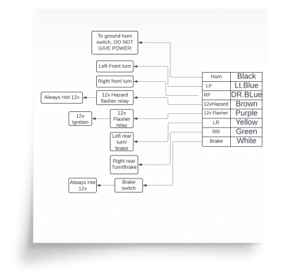
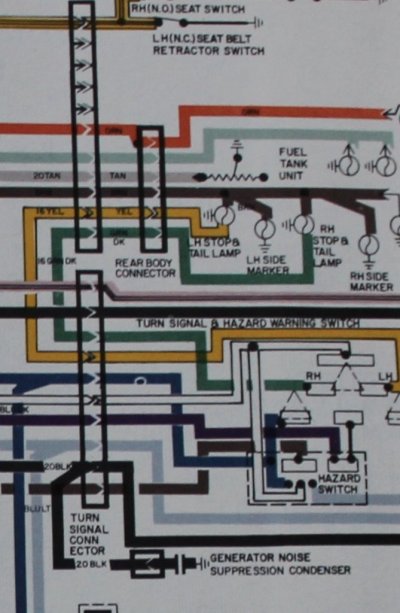
I have 84' C10 that is pretty much completely gutted inside and out, it has a Ls and 4l80e in it. Before this month it was wired awfully from the swap with a rat nest of unused wires hanging around under the dash. since its engine swapped and only has exterior lights, no blower radio dome light or anything else electrical i was only utilizing about 12 wires total (other than the ECM harness that is basically completely separate other than the ignition wire). I marked every wire i could and using the fuse box and a multi meter, and diagrams. Currently the only wires i need to use from the factory harness are the ignition wire (which I'm still using the factory ignition switch and have that wired), turn signals ( maybe hazard but don't care for it) wipers and brake switch for the rear brake lights. other than that i wire have the parking lights wired to the ignition wire from the ignition switch and headlights on a separate aftermarket switch. currently i have everything cut out except the i think 8 pin connection that runs up the column. I've found multiple diagrams but what i never understand about them is where they get power from, each wire is labeled to its respective place i.e rear right lamp turn signal and such. but the wires only come out of the column i have no idea where they are supposed to draw power from, since I'm wiring it with such few wires i have a OEM fuse box I'm running off the ignition wire to all these lights so i cant accidentally leave them on, but what wire in that 8 pin connector bring voltage in to distribute to the turn signals flasher and such, I've attached pictures of the only wires i plan on using if possible. thanks for any input as i continue to try and rewire this as simple but safe as possible.

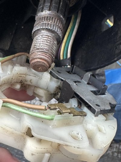
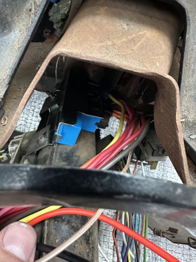
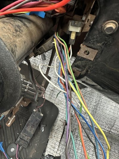
1st picture is the plug on the right side of the column. 2nd is of the ignition switch with plugs, 3rd is the wire at the steering wheel side of the column where they go into a component that has the blinker arms attached to.

Edit: yes i know i need to use a flasher relay and i haven't figured out exactly how that has to be wired into the turn signals for it to work, i have a led blinker laying around from the led lights i bought for it don't know if that will work or not but I'm prepared to figure out a way to use a normal blinker relay.
 

Attachments

  • unnamed (2).jpg
    unnamed (2).jpg
    133.2 KB · Views: 16
  • unnamed (1).jpg
    unnamed (1).jpg
    162.4 KB · Views: 17
  • unnamed.jpg
    unnamed.jpg
    210.4 KB · Views: 19

Matt69olds

Full Access Member
Joined
Jan 8, 2018
Posts
2,353
Reaction score
3,604
Location
Central Indiana
First Name
Matt
Truck Year
81
Truck Model
GMC 1/2 ton
Engine Size
455 Olds
Power comes into the truck on 2-3 heavy gauge red wires. One goes to the headlight switch and other items that are powered at all times, the other goes to the ignition switch. The ignition switch splits the power up by function. I don’t have any manuals handy, but I do remember an orange, brown, pink, and I think blue. I do know pink powers ignition related components. The orange powers things that are suppose to work in “Run”, I think the brown powers thinks that are intended to run with the key in “accessory”. There will also be a yellow or purple wire with yellow tracer, that’s your “crank” signal wire.

Before doing anything else, make sure you have the connectors to the ignition switch fully seated. Next, turn on the ignition, and use a test light to check for power on both sides of each fuse in the fuse box. Note that the fuse labeled “lamps” will only show power with the headlights on.

Once you have verified which fuses are powered and dead, it will be easier to figure out the next step.
 

Trenholm

Junior Member
Joined
Feb 5, 2022
Posts
3
Reaction score
0
Location
Minnesota
First Name
Joe
Truck Year
1984
Truck Model
c10
Engine Size
5.3
Power comes into the truck on 2-3 heavy gauge red wires. One goes to the headlight switch and other items that are powered at all times, the other goes to the ignition switch. The ignition switch splits the power up by function. I don’t have any manuals handy, but I do remember an orange, brown, pink, and I think blue. I do know pink powers ignition related components. The orange powers things that are suppose to work in “Run”, I think the brown powers thinks that are intended to run with the key in “accessory”. There will also be a yellow or purple wire with yellow tracer, that’s your “crank” signal wire.

Before doing anything else, make sure you have the connectors to the ignition switch fully seated. Next, turn on the ignition, and use a test light to check for power on both sides of each fuse in the fuse box. Note that the fuse labeled “lamps” will only show power with the headlights on.

Once you have verified which fuses are powered and dead, it will be easier to figure out the next step.
I gave up on googling answers and just put my multi meter to work, basically came to the conclusion GM is smart but also not obvious about where wires go, i attached a picture with a wiring scheme i drew up quick. I'm aware of what wires i need on the ignition switch it was only the wiring going up the column to the blinker assembly that tripped me up, 12v flasher is a supply wire Brake is a 12v supply wire only when the brake pedal is pushed and hazard is a 12v supply wire when the hazards are on. they switch responsibility of powering the rear turn/ brake wire through the blinker assembly. Guess sometimes you just got to figure stuff out the hard way but its done now and I'm onto wiring in my ECM Air ride ECU and compressors.
 

Attachments

  • c10 (1).png
    c10 (1).png
    297.6 KB · Views: 15

Matt69olds

Full Access Member
Joined
Jan 8, 2018
Posts
2,353
Reaction score
3,604
Location
Central Indiana
First Name
Matt
Truck Year
81
Truck Model
GMC 1/2 ton
Engine Size
455 Olds
The nice thing about GM is they have used the same basic wire colors for certain functions since the 50s.

This is a screenshot of a factory wiring diagram for a 72 Olds. I’m 99.9 percent sure these colors will match your trucks turn signal switch.
 

Trenholm

Junior Member
Joined
Feb 5, 2022
Posts
3
Reaction score
0
Location
Minnesota
First Name
Joe
Truck Year
1984
Truck Model
c10
Engine Size
5.3
The nice thing about GM is they have used the same basic wire colors for certain functions since the 50s.

This is a screenshot of a factory wiring diagram for a 72 Olds. I’m 99.9 percent sure these colors will match your trucks turn signal switch.
Didn't see the screenshot must not have loaded or something, but i pulled the wiring out of the frame and holy smokes previous owner had a hayday with duck take and solder. so I've taken it upon myself to replace every wire, no sense in replacing 10 ft of a 15 foot circuit, most of the wiring is factory and mildly rotted. so ill be making it in the house and looming it, until its warm and then install it in the truck.
 

Matt69olds

Full Access Member
Joined
Jan 8, 2018
Posts
2,353
Reaction score
3,604
Location
Central Indiana
First Name
Matt
Truck Year
81
Truck Model
GMC 1/2 ton
Engine Size
455 Olds
Let’s try this again!
 

Attachments

  • IMG_8497.jpeg
    IMG_8497.jpeg
    105.2 KB · Views: 10

Forum statistics

Threads
42,167
Posts
910,523
Members
33,663
Latest member
eatfood
Top