Ignition problem- New parts, no spark- 454 HEI

Disclaimer: Links on this page pointing to Amazon, eBay and other sites may include affiliate code. If you click them and make a purchase, we may earn a small commission.

HotRodPC

Administrator
Staff member
Admin
Joined
Aug 29, 2010
Posts
47,024
Reaction score
9,031
Location
OKC, OK
First Name
HotRod
Truck Year
85 K20 LWB
Truck Model
Silverado
Engine Size
454 - Turbo 400 - 3.73
OK. Worth checking in any case. It's cranking over just fine on the starter, though. Problem is it has no spark and won't fire off.

I understand that. But, power to the dizzy in most cases, does actually go through the starter solenoid.

It's been said many times, although not true, that the S on the solenoid means Start, and the R means Run. In older vehicles, you actually got 12 volts while cranking and as soon as the motor started, the power to the coil was cut to 6v. This could be done through the Solenoid to a RESISTOR WIRE, or a Ballast Resistor. Just suggesting to check it so that you know the ignition system is getting it's power to and through the solenoid.
 

suburble

Full Access Member
Joined
Sep 23, 2013
Posts
203
Reaction score
8
Location
Arizona
First Name
Josh
Truck Year
1986
Truck Model
Suburban C20
Engine Size
454
I understand that. But, power to the dizzy in most cases, does actually go through the starter solenoid.

It's been said many times, although not true, that the S on the solenoid means Start, and the R means Run. In older vehicles, you actually got 12 volts while cranking and as soon as the motor started, the power to the coil was cut to 6v. This could be done through the Solenoid to a RESISTOR WIRE, or a Ballast Resistor. Just suggesting to check it so that you know the ignition system is getting it's power to and through the solenoid.

I'll definitely give it a look, then.
 

chengny

Full Access Member
Joined
Feb 22, 2012
Posts
4,086
Reaction score
1,010
Location
NH
First Name
Jerry
Truck Year
1986
Truck Model
K3500
Engine Size
350/5.7
-Neutral safety switch is not the problem per functional testing; the starter turns the motor over just fine in P or N, but not in gear.

I just went back and read the "expert advice" I provided to help you with your no-spark issue - WTF was I thinking!

Needless to say; you can disregard everything I posted about the NSS having anything to do with the coil primary circuitry. The NSS/CSS are to the control circuit of the starter solenoid - they have nothing to do with the ignition system.

I apologize if I made you waste any time on a wild goose chase. I was trying to answer too many questions in a short period of time (and probably drank too many Natty Ice's in a short period of time as well).


Some info on the solenoid R & S terminals and how they relate to the ignition coil:
 

Attachments

  • solenoid terminals.jpg
    solenoid terminals.jpg
    83.1 KB · Views: 146
  • Sol Conns.jpg
    Sol Conns.jpg
    91.6 KB · Views: 237

chengny

Full Access Member
Joined
Feb 22, 2012
Posts
4,086
Reaction score
1,010
Location
NH
First Name
Jerry
Truck Year
1986
Truck Model
K3500
Engine Size
350/5.7
So... If I'm correct in assuming I should be seeing 12v at the plug in from the firewall to the distributor (which I am not seeing on my multimeter), then it should be either a bad ignition switch or a wiring issue (possibly the 2nd fusible link).

That would be correct. But then you also say/ask the following:

I'm assuming the 2-wire connector from the firewall is keyed 12v for the coil, and should show 12v across the 2 terminals when they key is at "start" or "run".

When I measured across those 2 terminals (with my wife inside the 'burb turning the key) I saw a small jump to about 1.5v when the key was first turned, then nothing.

Am I correct in thinking I should be seeing 12v?


That would be wrong. Checking for voltage across the terminals of the 2 wire plug would not show voltage even if it was available. The only wire you should be concerned with is the red wire (i.e. the one that clips onto the stab marked BATT.

If you look closley at the top of the square plug receptacle (it sticks out on the LH side of the coil cover) you should see 2 markings with a stab under the cap. One is labeled TACH (this is the impluse signal to any tachometer that may be installed), the other will be marked BATT (this is the power from the ignition switch to the coil).

The wire that connects to the stab under the BATT marking is where you will put the red probe of your meter.

The white wire has nothing to do with measuring coil supply voltage so disregard it.

What you need to do with the black test probe is touch it to a good, clean & and paint free area on the body or frame. Doing that will provide your meter with a proper ground.

With the black probe of the meter now connected to ground, the red probe in contact with the red wire in the harness plug and the meter set to VDC - turn the ignition key to the RUN position.

If everything is okay, you should get a reading of about 13.5 volts.
 
Last edited:

suburble

Full Access Member
Joined
Sep 23, 2013
Posts
203
Reaction score
8
Location
Arizona
First Name
Josh
Truck Year
1986
Truck Model
Suburban C20
Engine Size
454
The wire that connects to the stab under the BATT marking is where you will put the red probe of your meter.

The white wire has nothing to do with measuring coil supply voltage so disregard it.

What you need to do with the black test probe is touch it to a good, clean & and paint free area on the body or frame. Doing that will provide your meter with a proper ground.

With the black probe of the meter now connected to ground, the red probe in contact with the red wire in the harness plug and the meter set to VDC - turn the ignition key to the RUN position.

If everything is okay, you should get a reading of about 13.5 volts.

Yes! Thank you, that's what I was (unclearly) trying to ask. I need to re-measure, since I checked across the 2 terminals, and not red wire to ground. It sounds like my testing yesterday was not conclusive.

Thanks.
 

suburble

Full Access Member
Joined
Sep 23, 2013
Posts
203
Reaction score
8
Location
Arizona
First Name
Josh
Truck Year
1986
Truck Model
Suburban C20
Engine Size
454
OK, now we're getting somewhere. I retested with the meter between the red "batt" terminal at the distributor and a body ground and got 11.9v with the key at "run". Switched from body ground to negative battery terminal, same results- also 11.9v.

So... Is 11.9v enough to run the coil?

Thanks everyone for the help so far.

-Josh
 

chengny

Full Access Member
Joined
Feb 22, 2012
Posts
4,086
Reaction score
1,010
Location
NH
First Name
Jerry
Truck Year
1986
Truck Model
K3500
Engine Size
350/5.7
Yes, you're fine. The GM specified minimum primary coil voltage - that which is required to produce a "robust" spark in the ignition secondary (i.e. enough voltage to produce a bright blue arc across the spark plug gaps) - is 10.5 volts.

NOTE: While 10.5 is stated as the minimum primary voltage in some places, the diagnostic chart below specifies 7 volts as the minimum. Go figure.


Regardless, you are well above the minimum (at least during non-crank conditions). However, things can change when the key is moved to START and the starter motor places a large load on the entire electrical sysytem. Checking coil primary voltage - while cranking the engine with the starter - is the next step. Notice that it is also the first step in the diagnostic chart below:

Do the voltage test again, but this time take it one step further. While you observe the voltage across the red wire/ground test points, have an assistant crank the starter. While the starter is cranking watch the VOM closely. If it is a digital type it make take a second or so to re-calculate and display the change in voltage (if any). If you happen to have an analog multimeter (with a needle type indication) use it - any change in voltage will cause the needle to deflect downwards immediately.

After that - if there is no issue with voltage supply to the coil primary you need to start looking inside the distributor

Here is a description of operation for the GM HEI system:

The HEI system utilizes an all electronic module, pickup coil and timer core in place of the conventional breaker points, condenser and distributor cam. In addition, a specially designed ignition coil, distributor cap, rotor and high tension leads are used to provide and distribute high intensity secondary system voltages to the spark plugs. Typical HEI system components are illustrated in Figs. 1 and 2.
The magnetic pickup consists of a rotating timer core attached to the distributor shaft, a stationary pole piece, permanent magnet and pickup coil. When the distributor shaft rotates, the teeth of the timer core line up and pass the teeth of the pole piece inducing voltage in the pickup coil which signals the electronic module to open the ignition coil primary circuit. Since this is a full 12 volt system that does not use a resistance wire, high current saturation occurs in the coil primary windings. Maximum inductance occurs at the moment the timer core teeth are lined up with the teeth on the pole piece. At the instant the timer core teeth start to pass the pole teeth, the module opens the primary circuit, and the current decay causes a high voltage to be induced in the ignition coil secondary winding. The high secondary voltage is directed through a specially designed cap, rotor and high voltage leads to fire the spark plugs.
HEI systems use conventional vacuum and centrifugal advance mechanisms. The vacuum diaphragm is connected by linkage to the pole piece. When the diaphragm moves against spring pressure it rotates the pole piece allowing the poles to advance relative to the timer core. The timer core is rotated about the shaft by conventional advance weights, thus providing centrifugal advance.
Some models are equipped with and Electronic Spark Control (ESC) system that controls spark timing in order to provide maximum engine performance while preventing detonation. The ESC system consists of an engine mounted knock sensor and an electronic controller, Fig. 3. ESC is a closed loop system that monitors engine detonation through a sensor and constantly adjusts ignition timing to provide the maximum usable spark advance while preventing prolonged detonation.
The ESC knock sensor monitors the presence and intensity of engine detonation by sensing the resultant vibrations. The sensor produces a voltage signal which is proportional to the intensity of the detonation and this voltage signal is transmitted to the controller. The ESC controller is a hard wired signal processor/amplifier that operates in the 6-16 volt range, and has no memory storage provisions. The controller monitors knock sensor voltage output, processes these signals and controls the amount of spark advance through a special circuit in the HEI ignition module.
In addition, models with automatic transmissions include an ESC vacuum switch. The vacuum switch provides a signal to the ESC controller during throttle tip-in which causes the module to momentarily retard spark timing to prevent detonation on acceleration.

Component views and diagnostic chart for your particular type of ignition system - "HEI without ESC/EST and with Integral Coil":
 

Attachments

  • HEI dist_2016x1788.jpg
    HEI dist_2016x1788.jpg
    84.4 KB · Views: 202
  • Dist igntion comps_1056x842.jpg
    Dist igntion comps_1056x842.jpg
    94.3 KB · Views: 179
  • Diagnostic HEI non ESC & Integral Coil_1792x2504.jpg
    Diagnostic HEI non ESC & Integral Coil_1792x2504.jpg
    97.9 KB · Views: 229
Last edited:

chengny

Full Access Member
Joined
Feb 22, 2012
Posts
4,086
Reaction score
1,010
Location
NH
First Name
Jerry
Truck Year
1986
Truck Model
K3500
Engine Size
350/5.7
THE GM HEI SYSTEM

Any conversation about electronic ignition leads to the GM HEI, which is an abbreviation for high-energy ignition. Chrysler was the first company to offer electronic triggering to the masses; it was available on some models in 1972 and became standard across the board for the 1973 model year. Ford Motor Company made its Dura-Spark system standard in 1975, the same year that GM introduced HEI.
The attributes of electronic ignition, made possible by advances in transistor technology, finally answered the call to eliminate breaker points, and the undesirable features associated with them. The benefits of electronic ignition include:


· The elimination of wearable parts
· High voltage and current output
· Variable dwell instead of fixed dwell (coil saturation)
· The elimination of the resistor circuit
· Allowed for widened spark plug gaps to support leaner mixtures
· Minimized cross-firing (by increasing distributor cap post spacing)


With the arrival of the 1973-'74 energy crisis and the federal government's new fuel economy and emissions standards, the constant degradation of ignition output with breaker points needed to be eliminated. The problem was the constant wear they suffered. As the rubbing block wore, the ignition's output would diminish; additionally, a one-degree change in dwell would impact the ignition timing a like amount, which we'll explain in detail later in the article.

Another concern was the limited voltage input that a breaker ignition could take while still maintaining an acceptable lifespan. Due to the breaker's inability to withstand a constant 12 volts, a resistance circuit was required to reduce the primary voltage to approximately 7 volts. The power was supplied through the ignition switch, arranged so that the engine would crank on full battery voltage, but when the ignition key was released to the run position, the circuit would be redirected and the voltage dropped by a resistance wire or ballast resistor. Abiding by the laws of physics, this limited the spark output potential of the coil, along with the gap of the spark plug.


The HEI difference
When Delco set out to design HEI, it addressed all of the problems with points. By eliminating the mechanical breaker system and replacing it with a transistor that had no moving parts, HEI eliminated wear problems. The additional available energy allowed for a constant output with longer spark plug life and the wider gap that was needed to remain emissions compliant.

Additionally, HEI addressed limited output. It is possible to obtain higher secondary voltage by simply increasing the current in the primary circuit: Coil energy is equal to one-half of the coil inductance multiplied by the current squared. The higher current-carrying capabilities of a transistor over breaker points automatically increased the ignition output. In most breaker point systems, the primary current was limited to 3.5 to 4.0 amperes. Maximum point life was realized with only one ampere flowing across the contacts. As current increased, point life decreased steadily until just over four amperes was reached. Above this value, point life decreased dramatically.

Transistors don't have this limitation. A switching transistor can handle a full 12 volts with a current capacity of over five amperes. This allowed HEI to offer 40 percent more voltage output with 85 percent higher energy levels than the breaker point ignition it replaced.

For the ignition coil to produce maximum secondary voltage, the limit for primary current must be reached before the primary circuit is broken, allowing the field in the coil to collapse and discharge through the spark plug. In a points system, the length of time the primary current is turned on and charging the coil is referred to as "dwell" and is controlled by the cam in the distributor.

Dwell is defined as the degrees of distributor cam rotation the primary ignition circuit is turned on. Most V-8 engines using breaker points have a nominal dwell value of 30 degrees. The dwell angle remains constant regardless of engine rpm. As the speed of the engine increases, the length of physical time that the points are closed decreases. This reduces the available voltage and coil energy.

In a points ignition system, as the engine speed increases, the available energy to meet the demand of the spark plug decreases. HEI eliminated this problem by removing the resistance wire and applying full alternator output to the primary circuit.

Another unique feature of HEI is a dwell period that responds to changes in engine speed. Identified as an expanding dwell, the saturation time of the coil is controlled by engine rpm. At idle, an HEI system will experience a dwell time of 10 to 15 degrees and will increase to 30 to 35 degrees by 2,500 to 3,000 rpm. The ignition now has the output when the engine needs it--at high speeds and under load.

In a points system, it would take 10 milliseconds for the current to reach maximum with a coil that has 2.6 ohms of resistance. The primary windings of an HEI coil have only 0.5-ohm resistance, allowing maximum current to be reached in approximately 3.4 milliseconds. Because it takes less time to reach full coil potential, saturation can be obtained at much higher engine speeds.

A coil can be thought of as a checking account: the more you put in, the more you can withdraw. By increasing the primary voltage input, the secondary output is increased, but more important, the length of time that the spark can burn--and the amperage at which it burns--is also increased. Electricity is passive--it uses only what it needs to get the job done. As an example, an HEI system has the ability to produce 40,000 volts to the spark plug for short periods of time. This can be likened to a car that has a top speed of 150 mph. If the load on the engine only requires 6,000 volts to bridge the gap of the spark plug, that is all that is consumed. In the same manner, a 150-mph car can cruise at 65 mph, using only a small amount of its potential power.

This analogy can be modified to describe an ignition coil: It can produce low voltage for a long time period or high voltage for a short time. Instead of referencing mph, an ignition system is measured in milliseconds (ms) and degrees of crankshaft rotation (CA). As the electrical demand increases, the length of time the arc across the spark plug can be maintained decreases.

Attaching some numbers to this, an HEI system can arc a spark plug for 2ms and 20 degrees CA. A points ignition would, at best, only support approximately 1.1 to 1.5ms and 10 to 15 degrees CA. At higher engine speeds, the coil has less time to charge. There is even less energy available to keep the spark plug lit and turn the fuel into power.

Ford and Chrysler were not as ingenious with their electronic ignitions. While both were able to eliminate the issue of breaker-point wear, the Mopar unit, though transistorized, still used a ballast circuit, limiting spark output. Ford designed the Dura-Spark with full charging circuit voltage but maintained the fixed dwell period of points. As time went on, almost every automaker in the world copied the Delco HEI design; it is considered by many to be the father of all modern ignition systems.
 

chengny

Full Access Member
Joined
Feb 22, 2012
Posts
4,086
Reaction score
1,010
Location
NH
First Name
Jerry
Truck Year
1986
Truck Model
K3500
Engine Size
350/5.7
Servicing the HEI

Due to its trouble-free nature, the HEI is an often-neglected component. Since it is electronic, many people seem to believe that if it is working, all must be well. That may be the case, but once a problem does occur, it is important to be able to diagnose it. By following the steps in this primer, you will be able to accurately diagnose and repair any GM HEI system. We traveled to Classic Restoration Enterprises in Pine Island, New York, where technician Richard Wiegand worked with us using a brand-new ACCEL HEI unit to illustrate the inner workings of the HEI and how to service it.
There are three main components in an HEI: the ignition module, the pick-up coil and the integral high-tension coil. The other components of the distributor, such as the mechanical and vacuum advance, gear drive and shaft, are all very similar in function to those found on a breaker-point system. Comparing the HEI components to those in a conventional distributor makes it easier to understand and repair.
The ignition module can be thought of as the contacts of the breaker points, while the pick-up coil and reluctor (the tooth wheel on the distributor shaft) serves the same function as the distributor cam and rubbing block. Thus, for the module to charge and then collapse the coil, it needs to receive a signal from the pick-up coil. The output of the pick-up coil is identified as a saw-tooth sine wave and can be confirmed with a voltmeter.
You cannot check the module itself internally, so the diagnostic steps required generally involve confirming operation of everything else: If the other parts test fine, replace the module. Often, the diagnostic steps are skipped and the person working on the car assumes the module has failed, using parts replacement as a diagnostic procedure. The diagnostic steps allow you to avoid this practice.
Check the dwell on an HEI module to confirm the circuit is evoking the longer (expanding) dwell time as the engine speed is increased. To do this, connect a tune-up tach and dwell meter to the "TACH" terminal on the distributor cap and then start the engine. At idle on a V-8, the dwell with a Delco module should be between 10 and 15 degrees. As the engine speed is raised, the dwell should increase to 30 to 35 degrees by 2,500 rpm. If it does, the module is working properly.
Note that some aftermarket ignition modules do not provide the proper expansion of dwell: They often have an excessive amount at idle and provide little increase at high speeds. This can cause a misfire at high rpm, because the coil saturation is not sufficient. Conversely, if the dwell sticks on the module, the engine can exhibit a very rough idle with a dead misfire, hesitation at light load, pinging and overall poor performance. If the dwell period is incorrect, the diagnosis is simple: Replace the module.
The only time a properly working HEI module will show a fixed dwell of around 30 degrees is if an aftermarket CD ignition box, like an MSD or similar unit, is attached. The current draw of the CD unit will drive the module to a dwell period that is similar to that at high engine speeds in a stock application.
Ignition system design is still evolving today with distributor-less and coil-on-plug systems. With every new theory, the same basic premise still applies: Widen the gap of the spark plug to increase the ionization window and keep the plug arced for as long in the crankshaft's rotation as possible. Though no production version of the original HEI system is in use today, it was clearly a design that revolutionized the industry and laid the groundwork for today's modern ignition systems.


NOTE CORRESPONDING IMAGES ARE BELOW THE TEXT


The original HEI design featured an integral ignition coil and a one-wire hook-up of 12 volts. The cap is marked to identify the tach and voltage supply.

You must be registered for see images attach


The wide spacing of the secondary terminals in the cap was necessary to prevent cross-fire between cylinders and to eliminate arc-over to ground. This was due to the high output.

You must be registered for see images attach


The coil is retained by four screws. It is important to make sure the screws are the proper length and do not puncture the distributor cap above the rotor. The ground strap under the coil, which is used to bleed off any electrical charge that may accumulate in the coil's metal support frame, needs to be replaced.

You must be registered for see images attach


Once the coil is removed, the carbon button can be accessed. When installing a new cap, do not forget to install the new carbon button. Many leave the button out and the coil arcs to the rotor through the hole. The engine will start this way, but will misfire in a few miles.

You must be registered for see images attach

You must be registered for see images attach


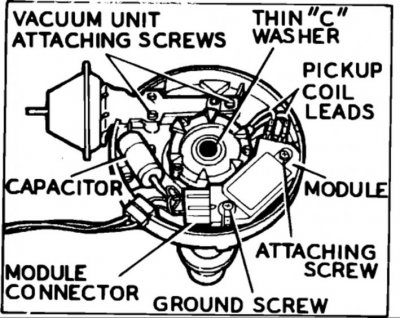
This is what you will see with the cap and rotor removed. The vacuum advance connects to the pick-up coil; those leads have a tendency to break from movement. This usually causes the engine to sputter, backfire and possibly stall at light load, though it will run fine at idle or full throttle. If this occurs, a quick diagnostic step is to disconnect the vacuum line so the advance does not function to see how the engine runs. The condenser is used for radio noise suppression.


You must be registered for see images attach


To remove the distributor advance weights, the springs need to be taken off their moorings by pulling and lifting up.

You must be registered for see images attach


You must be registered for see images attach


To remove the module, the leads from the pick-up coil need to be disconnected. Be gentle with the wires, especially with an older distributor.


You must be registered for see images attach


Once the screws are detached, the module can be removed. The underside should be coated with white grease, which is a heat-sink compound. When the compound gets old, it will become hard and ineffective in transferring heat. The result will be the loss of ignition at high temperature, as the module overheats.


You must be registered for see images attach


The module attaches to the heat sink and the compound helps transfer heat to the casting.

You must be registered for see images attach


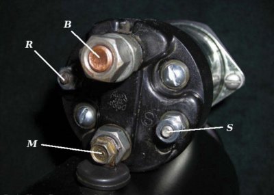
Always wipe off the old compound from the heat sink and module and apply a generous amount of new product. Make sure the product you use is listed as a heat transfer agent and not just dielectric grease. The tube should say "for use under ignition modules." To check the pick-up coil, attach an ohmmeter to the two leads, as seen in the lead photo of this article. The reading should be between 500 and 1,500 ohms. Make sure to jiggle the wires with the meter attached to test for any breaks.

You must be registered for see images attach


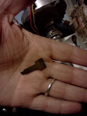
To service the pick-up coil, the distributor shaft needs to be removed. The first step is to knock out the roll pin that holds the distributor gear.

You must be registered for see images attach


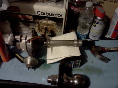
On an older distributor, you may need to soak the shaft and bushing with a product such as WD-40 to loosen any oil crud that would stop the shaft from lifting up.

You must be registered for see images attach


The shaft should pull straight out of the case. Be patient with the WD-40. If you drive the shaft out with a hammer and block of wood, you may pull the top bushing out of the case. Then you will need to buy a new distributor, because the bushing will likely spin if reinstalled.

You must be registered for see images attach


The pick-up coil is held in place by a blind snap-ring. Often, two picks work better to remove it than snap-ring pliers. Do not lose the clip, because some brands of pick-up coil do not include another one. The attachment to the vacuum advance is clearly seen in this image.

You must be registered for see images attach
 
Last edited:

suburble

Full Access Member
Joined
Sep 23, 2013
Posts
203
Reaction score
8
Location
Arizona
First Name
Josh
Truck Year
1986
Truck Model
Suburban C20
Engine Size
454
OK, been busy but I finally got around to working on the 'Burb.

Good news and bad news-

Good news- definitely seems to diagnose back to a bad pick-up coil. I have the new GM parts and the distributor is ready to stab back in.

Bad news- when I took the distributor out, a 1/2" long section of fossilized gasket teetered precariously and then dropped right down into the engine, no doubt chuckling evilly to itself the entire time.

How bad a situation am I in? I can't see the gasket piece with a flashlight and mirror. Is it a straight shot down into the oil pan? I sure don't want to put the distributor back in until I have that chunk back out or know it won't hurt anything.

Any advice?

I'm starting another thread to cover this, but figured I'd put it on here as well.

Thanks,
-Josh
 

suburble

Full Access Member
Joined
Sep 23, 2013
Posts
203
Reaction score
8
Location
Arizona
First Name
Josh
Truck Year
1986
Truck Model
Suburban C20
Engine Size
454
Well, I think I may have found the root cause of my problems.

When I pulled apart the distributor on the bench, the part below fell out. It looks to be the metal contact tang from a distributor cap, and it looks like it was sitting in between the timer core (toothed part on the dist. shaft) and the pole piece of the pickup coil.

Neither the old cap I removed or the new one I just put on are missing a tang like this, so it must have been in therefor quite a while.

Got it back together now, with all new Delco parts. I should be ready to stab it in by the weekend
 

Attachments

  • IMG_20140227_023134.jpg
    IMG_20140227_023134.jpg
    91.7 KB · Views: 125
  • IMG_20140227_023030.jpg
    IMG_20140227_023030.jpg
    91.4 KB · Views: 127

highdesertrange

Full Access Member
Joined
Dec 19, 2013
Posts
1,066
Reaction score
211
Location
kalifornia
First Name
mike
Truck Year
1978
Truck Model
k30
Engine Size
454
check the pick up assembly before you reinstall. I was going to suggest this was your problem. just did mine. highdesertranger
 

suburble

Full Access Member
Joined
Sep 23, 2013
Posts
203
Reaction score
8
Location
Arizona
First Name
Josh
Truck Year
1986
Truck Model
Suburban C20
Engine Size
454
check the pick up assembly before you reinstall. I was going to suggest this was your problem. just did mine. highdesertranger

I put in the new Delco pickup assembly that I had already bought, but that's a good idea. I'll at least ohm it out, maybe bench test it with a battery before I put it back in.

Thanks,
-Josh
 

suburble

Full Access Member
Joined
Sep 23, 2013
Posts
203
Reaction score
8
Location
Arizona
First Name
Josh
Truck Year
1986
Truck Model
Suburban C20
Engine Size
454
Well, got it back together and running well enough for a test drive. I had to put another distributor cap on it, because the screw holding the ground wire to the coil was stripped and the ground wire wasn't making good contact. Now I just have to set the timing and I should be ready to move on to the carb rebuild and fixing the exhaust leak.
 

chengny

Full Access Member
Joined
Feb 22, 2012
Posts
4,086
Reaction score
1,010
Location
NH
First Name
Jerry
Truck Year
1986
Truck Model
K3500
Engine Size
350/5.7
Good job with a good final outcome.

You did a thorough diagnostic procedure and did not resort to a "shotgun repair" (i.e. replacing all associated parts and hoping it works).

As a bonus, you probably know as much - or more - about the HEI system as anyone you'll ever meet.
 

Latest posts

Forum statistics

Threads
42,342
Posts
914,018
Members
33,844
Latest member
aaron06
Top