1987 tbi stalls under load, idles rough when cold

Disclaimer: Links on this page pointing to Amazon, eBay and other sites may include affiliate code. If you click them and make a purchase, we may earn a small commission.

GoBucs

Junior Member
Joined
Feb 13, 2013
Posts
16
Reaction score
0
Location
Laurel, md
First Name
Nick
Truck Year
1987
Truck Model
K10
Engine Size
350
Sorry if this is in the wrong spot, didn't know where to put it.

truck is an 87 k10 with a 350 tbi. All stock minus headers. sm465.

Just got done replacing a burnt exhaust valve in the number 1 cylinder and now it wont run right. Takes forever to crank and idles rough/stumbles when cold. Once it warms up the truck idles fine. Get it on the road and it almost dies when its put under load. Smells like its running rich. Double checked all my vacuum lines, all are connected and tight, Timing is set to 0 (the correct way with the wire unplugged). Even tried advancing alittle but it didnt help. Plugs, cap, rotor, wires all new. The icm is new as well. Injectors both have a good cone pattern, valves are adjusted correctly. There are no codes whatsoever. This thing has me stumped. I've yet to check fuel pressure, that's probably what ill do next. The o2 sensor being further down on the headers has me thinking that might be part of my cold start issue, but i'm not sure. Any help would be appreciated.

thanks,
Nick
 
Last edited:

brianhannon

Member
Joined
Dec 4, 2014
Posts
36
Reaction score
16
Location
White Hall, Maryland
First Name
Brian
Truck Year
1975
Truck Model
c10
Engine Size
383/ TH350/10 Bolt
Nick,

Didn't have any issues before? This just started after the valve work was done?


Brian
 

GoBucs

Junior Member
Joined
Feb 13, 2013
Posts
16
Reaction score
0
Location
Laurel, md
First Name
Nick
Truck Year
1987
Truck Model
K10
Engine Size
350
No it was there, however much more pronounced as it had little to no compression in the one cylinder.
 

350runner

Full Access Member
Joined
Feb 9, 2013
Posts
2,858
Reaction score
224
Location
tx
First Name
Ceasar
Truck Year
82
Truck Model
c10
Engine Size
350
Valve lash?

Sent from the dust in front of you!
 

GoBucs

Junior Member
Joined
Feb 13, 2013
Posts
16
Reaction score
0
Location
Laurel, md
First Name
Nick
Truck Year
1987
Truck Model
K10
Engine Size
350
All valves in the effected cylinder head were lapped, lash was set with the engine running to a half turn past zero. I believe i did it right, i'll have to double check.
 

350runner

Full Access Member
Joined
Feb 9, 2013
Posts
2,858
Reaction score
224
Location
tx
First Name
Ceasar
Truck Year
82
Truck Model
c10
Engine Size
350
@MadOgre

Sent from the dust in front of you!
 

chengny

Full Access Member
Joined
Feb 22, 2012
Posts
4,086
Reaction score
1,008
Location
NH
First Name
Jerry
Truck Year
1986
Truck Model
K3500
Engine Size
350/5.7
Was the reason that the valve originally burned up ever identified? I ask because your current issue sounds like a text book case of a sticking exhaust valve.
 

GoBucs

Junior Member
Joined
Feb 13, 2013
Posts
16
Reaction score
0
Location
Laurel, md
First Name
Nick
Truck Year
1987
Truck Model
K10
Engine Size
350
Sure wasnt. i had an extra set of tbi heads (albiet high mileage) laying around so i freshed one up and slapped it on. Took it apart, checked for trueness, cleaned it up in the parts washer, lapped the valves and reassembled. Was the cheapest route to a running truck, as im building another motor and wanted to have a running truck in the meantime. The truck did overheat pretty good once due to the lower radiator hose popping off on the highway. Compression tested good in every cylinder but number 1, leak down helped, oil wasnt milky...so i pulled the head and found the valve. Suppose I'll check the other bank and see if all my valves are moving as they should.
 

rich weyand

Full Access Member
Joined
May 28, 2014
Posts
964
Reaction score
162
Location
Bloomington Indiana
First Name
Rich
Truck Year
1978
Truck Model
K10
Engine Size
350
Lash was set with the engine running? That's wrong.

Per the manual:

- With the engine in #1 firing position, the following valves may be adjusted: Exhaust 1, 3, 4, 8 and Intake 1, 2, 5, 7.

- With the engine in #6 firing position, the following valves may be adjusted: Exhaust 2, 5, 6, 7 and Intake 3, 4, 6, 8.

- Back out adjusting nut until lash is felt at the push rod, then turn in adjusting nut until all lash is removed. This can be determined by rotating push rod while turning adjusting nut. When play has been removed, turn adjusting nut in one full additional turn.

Some people prefer only 3/4 additional turn.

Anyway, adjusting lash with the engine running is wrong. Fix that first. It's free.
 

GoBucs

Junior Member
Joined
Feb 13, 2013
Posts
16
Reaction score
0
Location
Laurel, md
First Name
Nick
Truck Year
1987
Truck Model
K10
Engine Size
350
Thanks. I will try that method.
 

chengny

Full Access Member
Joined
Feb 22, 2012
Posts
4,086
Reaction score
1,008
Location
NH
First Name
Jerry
Truck Year
1986
Truck Model
K3500
Engine Size
350/5.7
If you plan to redo the valve lash process, there are a couple of things worth mentioning:

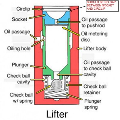
Before you begin, it is vital that the lifter pre-load that you previously applied is completely released. Work around the engine and back off all the rocker adjusting nuts. Allow some time for the plunger springs to drive the plungers to the very top of their strokes. The socket ( the cup that the pushrod rides in) of a fully decompressed hydraulic valve lifter will be hard up against the bottom of the circlip. See the image below.

Also, be aware that this process is a one shot deal. By that I mean; once the spring is compressed - whatever you use, 1/2 or 3/4 turns past zero lash - you cannot go back around the rocker nuts and .... let's say - "check your work". That is, unless you start all over again by releasing any applied preload.

However, before you close everything up and start the engine, there are a couple of things you can check to verify that you have properly preloaded the lifters:

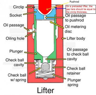
With the lifter off-stroke (i.e on the heel of the cam), check the gap between the socket and the bottom of the circlip. When it was unloaded, the gap should have been zero. Now, with the proper pre-load applied, the gap should be virtually identical to the cross-sectional diameter of the circlip. I don't know whether this is by design - or just a lucky co-incidence - but it is a valid check of proper pre-load/valve lash on a GM hydraulic lifter. See the second image below.

A second quick check is to apply pressure to the pushrod side of the rocker (again with the lifter off-stroke). The socket and plunger should move downward easily (the plunger springs are tiny and weak). The distance you can depress the plunger should be the same as the gap between the socket and circlip. IOW the proper preload will position the plunger at exactly the mid-point of it's total possible stroke.
 

Attachments

  • Start.jpg
    Start.jpg
    77.9 KB · Views: 106
  • Lift prelaod.jpg
    Lift prelaod.jpg
    79.9 KB · Views: 108
Last edited:

350runner

Full Access Member
Joined
Feb 9, 2013
Posts
2,858
Reaction score
224
Location
tx
First Name
Ceasar
Truck Year
82
Truck Model
c10
Engine Size
350
@chengny is spot on with the valve adjustment. Trying to set valve lash with the vehicle running is not correct and will lead to failure of the valve train. Valve Lash Adjustment Video - Engine Building Car…: http://youtu.be/89o5rLpbCgI
The way rich is speaking about works unless you have a cam with a lot of duration.

Sent from the dust in front of you!
 
Last edited:

MadOgre

Full Access Member
Joined
May 4, 2014
Posts
4,090
Reaction score
49
Location
NA
First Name
NA
Truck Year
NA
Truck Model
NA
Engine Size
NA
Its a lot easier to start at the #1 cylinder and adjust both valves then turn the crank 90 Degrees and do the next cylinder in the firing order 1-8-4-3-6-5-7-2.

When at TDC both the Intake and Exhaust valves are fully seated in the closed position which is what is required to be able to adjust to the proper tension on the lifter.

So you can do different valves independently as long as they are seated closed but it can get confusing so I just stick with one at a time. Besides all the extra work is supposed to keep a guy from gettin fat! :)
 

MadOgre

Full Access Member
Joined
May 4, 2014
Posts
4,090
Reaction score
49
Location
NA
First Name
NA
Truck Year
NA
Truck Model
NA
Engine Size
NA
If you plan to redo the valve lash process, there are a couple of things worth mentioning:

Before you begin, it is vital that the lifter pre-load that you previously applied is completely released. Work around the engine and back off all the rocker adjusting nuts. Allow some time for the plunger springs to drive the plungers to the very top of their strokes. The socket ( the cup that the pushrod rides in) of a fully decompressed hydraulic valve lifter will be hard up against the bottom of the circlip. See the image below.

Also, be aware that this process is a one shot deal. By that I mean; once the spring is compressed - whatever you use, 1/2 or 3/4 turns past zero lash - you cannot go back around the rocker nuts and .... let's say - "check your work". That is, unless you start all over again by releasing any applied preload.

However, before you close everything up and start the engine, there are a couple of things you can check to verify that you have properly preloaded the lifters:

With the lifter off-stroke (i.e on the heel of the cam), check the gap between the socket and the bottom of the circlip. When it was unloaded, the gap should have been zero. Now, with the proper pre-load applied, the gap should be virtually identical to the cross-sectional diameter of the circlip. I don't know whether this is by design - or just a lucky co-incidence - but it is a valid check of proper pre-load/valve lash on a GM hydraulic lifter. See the second image below.

A second quick check is to apply pressure to the pushrod side of the rocker (again with the lifter off-stroke). The socket and plunger should move downward easily (the plunger springs are tiny and weak). The distance you can depress the plunger should be the same as the gap between the socket and circlip. IOW the proper preload will position the plunger at exactly the mid-point of it's total possible stroke.

Just to add to Jerry as no one has actually laid out the process.


Well you have to do it with the engine off and you start with #1 cylinder at TDC and what you do is back off the rocker arm. Now spin the push rod with your fingers while tightening the rocker arm at the same time. As soon as you feel the push rod stops spinning freely the lash is removed. Then tighten an additional 3/4 turn and your done.

Both the intake and the exhaust valve can be done on each cylinder at the same time

Now turn the crankshaft 90 degrees clockwise so that the #8 cylinder is at TDC and repeat.

Repeat all 8 cylinders in order of the firing order 1-8-4-3-6-5-7-2

You can use the rotor on the distributor to ensure you have the correct cylinder. Also at TDC both the intake and exhaust valve springs will be fully extended as both valves will be closed
 

Latest posts

Forum statistics

Threads
42,222
Posts
911,658
Members
33,727
Latest member
Ls85c10man
Top