Help with 85 wire harness on engine swap?

Disclaimer: Links on this page pointing to Amazon, eBay and other sites may include affiliate code. If you click them and make a purchase, we may earn a small commission.

JustJohn

Junior Member
Joined
Feb 22, 2016
Posts
26
Reaction score
9
Location
Greenville
First Name
John
Truck Year
1985
Truck Model
C10
Engine Size
350
I just got this thing from someone who couldn't finish the project and I'm chasing some basic issues from an engine swap (stock 350 to 454).
First thing is brake lights, I checked back to front and came through the firewall to find connectors with their missing mates. Probably why I don't have AC controls or cluster lights too... Can anyone help me ID these connectors and where their mates might be?
 

Attachments

  • C10_drvr_connectors.jpg
    C10_drvr_connectors.jpg
    88.9 KB · Views: 473
  • C10_pass_connectors.jpg
    C10_pass_connectors.jpg
    80.5 KB · Views: 469

chengny

Full Access Member
Joined
Feb 22, 2012
Posts
4,086
Reaction score
1,008
Location
NH
First Name
Jerry
Truck Year
1986
Truck Model
K3500
Engine Size
350/5.7
I know what one of the connectors is for (the easiest one). The connector shown below is the split/splice point for the A/C compressor. A light green lead comes through the firewall from the HVAC control panel, it goes to that connector and splits off and heads over to the low pressure control switch on the receiver. It exits the control switch as a dark green and is supposed to go back to that connector and enter on the other side. Problem is I can't see that dark green lead alongside the pair of light greens. The red arrow shows where it is meant to go:

You must be registered for see images attach


Here is the plug with both sides wired up:

You must be registered for see images attach
 

JustJohn

Junior Member
Joined
Feb 22, 2016
Posts
26
Reaction score
9
Location
Greenville
First Name
John
Truck Year
1985
Truck Model
C10
Engine Size
350
Thanks, that gets me a start - no AC compressor at the moment. Power to the brake lights is the big one. I'd prefer to wire it back like the factory had it.
 

chengny

Full Access Member
Joined
Feb 22, 2012
Posts
4,086
Reaction score
1,008
Location
NH
First Name
Jerry
Truck Year
1986
Truck Model
K3500
Engine Size
350/5.7
Power to the brake lights:

Normally, I would say first check the fuse. But if that fuse was blown you would also not have parking lights (or under dash courtesy lights) and you didn't mention those being out.

So, assuming the fuse is good, I would start ringing this circuit out at the brake light switch - it is easy to access and simple to test.

Brake light circuit is hot at all times regardless of ignition switch position.

Go under the dash and locate the brake light switch (not the e-brake warning switch):

You must be registered for see images attach


The orange wire should be hot at all times. Check it for 12 VDC.

If you see power on the orange, test the switch.

Push down on the brake pedal and, while holding it down, check for voltage at the white lead.

If you have 12 VDC on the white, you have proven the circuit all the way up to the directional switch.

Do you have directionals but not brake lights? If so there is a problem within the directional switch. Let us know and someone will help.
 

JustJohn

Junior Member
Joined
Feb 22, 2016
Posts
26
Reaction score
9
Location
Greenville
First Name
John
Truck Year
1985
Truck Model
C10
Engine Size
350
Thanks! I've actually gotten my meter out previously and traced no power to the orange wire, continuity at the brake light ground wire. I followed it into the engine bay and it doesn't seem to be plugged in to anything. (maybe)

Now that I re-read your response, I see I might be looking at the directional switch. I do have a turn signal on one side and marker lights.
 

Boone83K10

Full Access Member
Joined
Feb 4, 2013
Posts
841
Reaction score
42
Location
Boone, NC
First Name
Benjamin
Truck Year
1983
Truck Model
K10
Engine Size
350
attachment.php


middle connector is to plug into a 700r4. it goes down to the driver side of transmission.

top connector is EGR bleed solenoid connector.

bottom connector is (I'll think of it soon)

attachment.php


4 prong connector with green is your fuel tank selector valve connector

oval shaped connector is your knock sensor

chengny got the third one.
 

JustJohn

Junior Member
Joined
Feb 22, 2016
Posts
26
Reaction score
9
Location
Greenville
First Name
John
Truck Year
1985
Truck Model
C10
Engine Size
350
I continue to be impressed...

Since it has a 454 and TH400 transmission, I think most of those are now moot.

I didn't realize there were dual tanks - the gauge seems to be working but I guess no idea what information I'm getting. That one at least is a candidate for finding its mate.

Other than that I think I now have a few days worth of effort getting a new signal switch and stalk installed. That will get me street legal enough to drive it to work.
 

Boone83K10

Full Access Member
Joined
Feb 4, 2013
Posts
841
Reaction score
42
Location
Boone, NC
First Name
Benjamin
Truck Year
1983
Truck Model
K10
Engine Size
350
I made a boo boo. The green 4 prong is not fuel selector connector. It would be 5 prong if it was...sorry

Sent from my SM-G920V using Tapatalk
 

Boone83K10

Full Access Member
Joined
Feb 4, 2013
Posts
841
Reaction score
42
Location
Boone, NC
First Name
Benjamin
Truck Year
1983
Truck Model
K10
Engine Size
350
The 4 prong is the ESC distributor plug. Throw it away, along with the knock sensor. I cant put my finger on that red connector. It is related to the entire harness in the pic. The white 700r4 is connected to the vacuum switch located at the 10 o clock area of the brake booster. The egr bleed solenoid connector is tied into that along with that red connector which I cant think of what it is. If you have a TH400, all of it can come out.

Sent from my SM-G920V using Tapatalk
 

chengny

Full Access Member
Joined
Feb 22, 2012
Posts
4,086
Reaction score
1,008
Location
NH
First Name
Jerry
Truck Year
1986
Truck Model
K3500
Engine Size
350/5.7
Back to the brake lights.

You say this:

Thanks! I've actually gotten my meter out previously and traced no power to the orange wire, continuity at the brake light ground wire. I followed it into the engine bay and it doesn't seem to be plugged in to anything. (maybe)


Sounds as if you're confusing two different circuits.

First. The orange wire that goes to the switch under the dash is power to the brake lights - those are the lights that others see when you step on the brakes. And if there is no voltage on that orange wire, don't order a new directional switch yet. You have a problem somewhere between the battery/fuse block and the brake pedal switch. That is actually good news. Changing the directional switch is a pain in the ass and should only be done if everything else checks out.


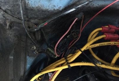
Second. The lead that goes through the firewall and terminates in the engine compartment is for the brake failure warning lamp on the dash. It should be tan and connects to the single male spade terminal on the wire mounted to the frame as shown:

You must be registered for see images attach


On the other side of the bracket/connector, the wire goes to a switch in the BPC (brake proportioning compensating) valve.

You must be registered for see images attach


If a major loss of hydraulic pressure occurs in the braking system the switch closes and grounds that lead. That ground will illuminate the brake lamp in the instrument panel. BTW - the same dash lamp is used to indicate when the e-brake is engaged - but through a separate switch mounted on the parking brake engaging mechanism.

Back to the brake lights - and BTW, disregard what I said above about the courtesy and parking lights. They are not on the same fuse/circuit as the brake lights. The only other thing on the same circuit as the brake lights is the hazards lights.

Do you have hazard flashers? If the brake lights and emergency flashers are out, check the STOP-HAZ. It's the 3rd fuse up from the directional flasher on the main fuse block:

You must be registered for see images attach


If the fuse looks good, pull it and test for voltage at the line side of the socket. That should be the RH side looking forward. But check both sides, the wiring diagrams are not always perfect.

If there is no voltage at the STOP-HAZ fuse socket, you will next need to check the fusible links. Start at the firewall junction block.

You must be registered for see images attach


See if there is power into and out of the JB. If there is power at the RH stud (looking aft), check the fusible link. It's supposed to be obvious when they are burnt but do not always show a failure. Pierce the insulation where shown and check for voltage there.

If there is no power on the JB'S LH stud, there is another fusible link down near the starter solenoid that you will need to check.
 
Last edited:

JustJohn

Junior Member
Joined
Feb 22, 2016
Posts
26
Reaction score
9
Location
Greenville
First Name
John
Truck Year
1985
Truck Model
C10
Engine Size
350
Thanks - I'll chase it down this weekend.

Incidentally, I do have hazard lights but the switch is screwed up. Easy to turn on, hard to turn off. There don't *appear* to be hacked up connections but I'm just getting into it.
 

chengny

Full Access Member
Joined
Feb 22, 2012
Posts
4,086
Reaction score
1,008
Location
NH
First Name
Jerry
Truck Year
1986
Truck Model
K3500
Engine Size
350/5.7
If you do have hazard flashers, I would double check the orange wire at the brake lights switch for voltage. That 140 orange circuit is probably the simplest wiring in the truck.

Out of the STOP-HAZ fuse and to a splice. Coming out of the splice, one leg goes to the hazard flasher and the other goes to the brake light switch on the pedal. That's the entire circuit.
 

JustJohn

Junior Member
Joined
Feb 22, 2016
Posts
26
Reaction score
9
Location
Greenville
First Name
John
Truck Year
1985
Truck Model
C10
Engine Size
350
If you do have hazard flashers, I would double check the orange wire at the brake lights switch for voltage. That 140 orange circuit is probably the simplest wiring in the truck.

Out of the STOP-HAZ fuse and to a splice. Coming out of the splice, one leg goes to the hazard flasher and the other goes to the brake light switch on the pedal. That's the entire circuit.

Thank you for detailing this out so well. I am a mechanical engineer and typically run away from electrical problems.

I have brake lights now! I was confusing the low pressure switch with the stop light switch and was able to confirm the circuit had power. Continuity was good between all the grounds and it did turn out to be the turn signal switch. I had already ordered an OE unit and had it ready to put in. Maybe I got lucky but the job wasn't too bad.

The only thing not quite right is the travel on the switch cam. The signal lever doesn't quite press down far enough to lock the left turn. It can be held down to function though.

Also gave the brakes a real pressure bleed. They still feel like truck brakes but much better than the only other GM truck brakes I've worked on, a 96 Tahoe. Mush.
 

Forum statistics

Threads
42,124
Posts
909,595
Members
33,615
Latest member
Jakebr8k
Top