1985---87
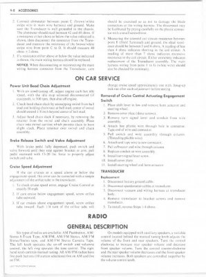
Servo Unit Adjustment
To adjust servo on V8 gasoline engines, close throttle, then with ignition and fast idle off, adjust rod assembly length to give .020---.040 inch clearance between rod and stud.
Engagement-Cruising Speed Zeroing
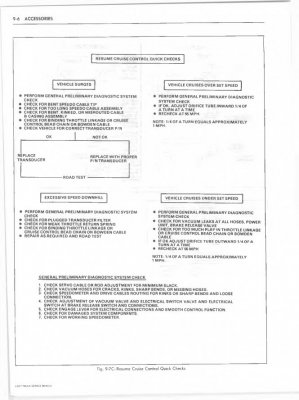
There is no provision for engagement-cruising speed zeroing. If cruising speed is too high or low, check vacuum hoses for improper routing, restrictions or leaks and servo linkage for proper adjustment. If cruising speed remains too high or low, replace the electronic controller.
General info and operation:
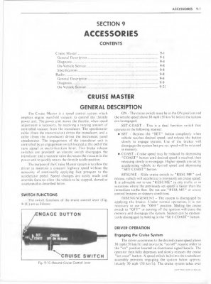
The Cruise Master system, used on 1983---87 models except 1983 Caballero and El Camino, allow the operator to maintain a constant vehicle speed without continually applying foot pressure on the accelerator pedal. Both systems use vacuum to control a servo unit which alters throttle position to maintain the selected speed, release valves and switches which allow the system to be easily disengaged, and dash or steering column switches to control the system.
1983---87 CUSTOM CRUISE III Operation:
This system consists of a mode control assembly, electronic controller (module), Vehicle Speed Sensor (VSS) buffer amplifier, servo unit, and release switches and valves. The servo unit maintains vehicle speed (throttle position) by trapping vacuum in its diaphragm chamber at servo positions determined by the control module. The module monitors mode control switch position, signals from the VSS buffer amplifier, servo position and release switch operation, then operates vacuum valves within the servo unit to control servo operation and vehicle speed. The module also contains a speed limiting function which prevents system operation at speeds below approximately 25 m.p.h..
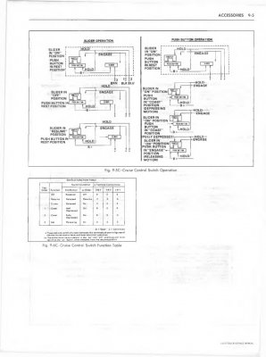
The mode control assembly, Fig. 5, consists of a 3 position slide-type switch and a set/coast switch button. To operate the system, the slide switch must be in on position and vehicle speed must be above 25 m.p.h.. The system is engaged at the desired speed by fully depressing, then releasing the set/coast button. Cruise speed can be increased from set position by accelerating vehicle to desired speed, then pressing and releasing button. In order to decrease speed, the set/coast button is held in the fully depressed position (disengaging system), then released when the desired speed is reached. The system can be disengaged at any time by depressing the brake or clutch pedal, or by moving the slide switch to off position.
If the system is disengaged by depressing the brake or clutch pedal, the last set speed will be retained in the module memory until the slide switch or ignition switch is moved to off position. Momentarily moving the slide switch to the resume/accel. position will cause the vehicle to accelerate to the last set speed and maintain that speed. If the slide switch is held in the resume/accel. position, the vehicle will continue to accelerate until the switch is released. When the switch is released, the speed that the vehicle accelerated to becomes the new set speed.
The slide switch also allows a ``tap-up'' function to increase cruise set speed in 1 m.p.h. increments. With the cruise control engaged and operating, ``tapping-up'' is done by pressing the slide switch to the resume position, then quickly releasing it. This procedure can be repeated 10 times before the system must be reset to a new speed in the conventional manner.
You must be registered for see images attach
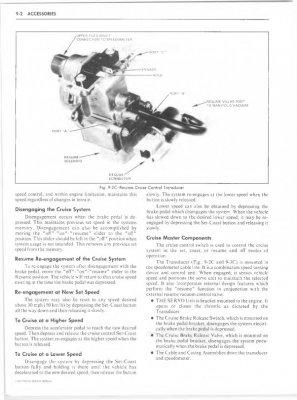
Servo Unit Operation:
The servo, Fig. 6, consists of a vacuum operated diaphragm, a normally open solenoid valve to vent the diaphragm, a normally closed solenoid valve connecting the diaphragm chamber to the vacuum source, and a variable inductance position sensor that provides the module with servo position data. The servo operates the throttle in response to control module commands as follows:
When the system is engaged and operating at a steady rate of speed, both solenoid valves are closed. Vacuum is trapped in the diaphragm chamber exerting a constant force on the diaphragm and the throttle position remains fixed.
When the vehicle is losing speed due to increased load, or when the operator seeks to increase speed through the control switch assembly, the module energizes the vacuum valve solenoid. This increases the force exerted on the diaphragm, which in turn increases the throttle opening.
When vehicle speed increases above the pre-set cruise speed, or when the operator seeks to decrease speed through the control switch assembly, the module de-energizes the diaphragm vent valve solenoid. This opens the valve, decreases force on the diaphragm, and allows the throttle return spring to decrease the throttle opening.
During normal operation, the module will pulse the operation of the vent or vacuum valves, as needed, to maintain the set cruise speed. The average duration of each pulse is 10 milliseconds. If vehicle speed drops 5 m.p.h. below set cruise speed, the module will hold the vacuum valve in the completely open (energized) position. If vehicle speed exceeds set cruise speed by 3 m.p.h. or more, then module will hold the vent valve in the open (de-energized) position. The module will hold the valves open until the vehicle speed matches the set cruise speed. The diaphragm vent valve will also remain in the fully open position if the brake or clutch pedal is depressed, the ignition is switched off, or if an open circuit exists in the system feed circuit or in the servo position sensor.
You must be registered for see images attach
You must be registered for see images attach


 So I cannot see them.