This may be good for future reference. I'll post a link and copy/paste it as well. Never know if it's TOO useful and they drop the site.
https://etesupport.zendesk.com/hc/en-us/articles/212564998-Install-Guide-6L80-6L90-GM-Automatic-Transmission-
Pasted:
CONTENTS
• Pre-Installation Tips
• Fluid Check Procedures
• Reflashing Guidelines
• Service Fast Learn Adapts
• Garage Fast Learn Adapts
• Installation Checklist
• Troubleshooting Guide
PRE-INSTALLATION
Prior to installation of the replacement transmission, determine the cause(s) of failure of the previous unit. Also:
• Check transmission cooler for glycol and/or water contamination
• Scan vehicle computer, record any codes, and fix all causes of codes before installation of replacement transmission
A restricted and/or contaminated transmission cooling system is the #1 cause of transmission failure after a replacement.
If the transmission cooler has evidence of transmission hard parts failure, it must be replaced. Plate-type oil-to-air (OTA) transmission coolers must always be replaced.
Entire transmission cooling system must be completely cleaned, hot flushed, and flow tested.
FLUID CHECK PROCEDURE
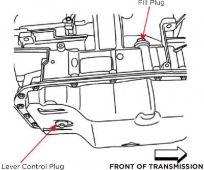
6L80 / 6L90 transmissions do not typically use a dipstick. Proper fluid level is achieved when fluid begins to drip from the Level Control Plug opening.
Verify vehicle is on level ground when performing fluid level check procedure.
Verify drive wheels are blocked and parking brake is applied.
Verify engine is idling at 0% throttle.
Verify transmission fluid temperature (TFT) is between 86°F and 122°F.
Shift transmission through entire range – hold in each range for at least three (3) seconds. When complete, shift vehicle back into PARK.
Remove Fill Plug. Remove Level Control Plug.
If fluid does not drip from hole (underfill condition), add fluid until fluid drips slightly from hole.
If fluid runs from hole when Level Control Plug is removed (overfill condition), allow fluid to flow until only a slight drip remains.
Reinstall Level Control Plug. Reinstall Fill Plug.
DO NOT OPERATE VEHICLE BEFORE OR AFTER PROPER FLUID LEVEL HAS BEEN ESTABLISHED.
As needed, fill transmission only with purchased synthetic or Dexron VI fluid. This transmission will require approximately 10 quarts of fluid.
REFLASHING GUIDELINES
This is an electronically-controlled transmission. The following information is VERY important to understand and to perform the procedures correctly. Failure to do so may cause damage to your new transmission and/or be the main cause for performance problems.
Check for proper installation of all vehicle ground connections. Erratic transmission performance may be caused by faulty ground(s) at various connection locations under the hood.
Inspect transmission wiring harness for damaged wires or connectors. Verify proper function of the entire electrical system including the battery, alternator, mass air flow sensor, and throttle position sensor.
Verify battery has proper charge before attempting reflash. Before starting reflash procedure, battery voltage should be between 12VDC – 16VDC. If battery voltage is low, charge battery BEFORE initiating reflash process. DO NOT INSTALL BATTERY CHARGER AT ANY TIME DURING THE REFLASH PROCESS.
Tools Required for Reflash
• Pass-thru J2534-compliant vehicle reflash hardware such as CarDAQ-Plus or equivalent:
http://www.drewtech.com/products/cardaqplus.html
• GM / AC Delco Service reprogramming subscription
• Hi-speed internet connection
• PC with Windows 7 / USB port / sufficient USB cabling to reach between PC and vehicle
Reflash Procedure
Please note: Your local dealership can perform the following steps for a nominal charge, after trans installation. If you do not have the proper equipment, do not attempt to perform these procedures.
Visit the GM web site
http://tis2web.service.gm.com/tis2web to verify whether or not the vehicle’s Engine Control Module (ECM) has the latest software updates and
calibrations to ensure proper transmission operation and shift quality.
Start and follow prompts on GM Service Programming System (SPS) site.
Verify that the Engine Control Module (ECM) and Transmission Control Module (TCM) are programmed to the latest available factory OEM calibrations. If not programmed properly, the Malfunction Indicator Lamp (MIL) warning light on the dash may illuminate, and the powertrain may only operate in fail-safe or “limp” mode.
The TCM cannot be reflashed independently – it must be reflashed at the same time as the ECM.
Powertrains equipped with aftermarket calibrations will
void the warranty.
SERVICE FAST LEARN ADAPTS
After installing the replacement transmission and ECM/TCM calibrations are complete, perform a vehicle Service Fast Learn Adapts procedure:
Verify vehicle is on level ground when performing relearn procedure.
Verify drive wheels are blocked and parking brake is applied.
Verify engine is idling at 0% throttle with no external engine rpm control.
Verify transmission fluid temperature (TFT) is between 158°F and 239°F.
Perform three (3) cycles of PARK – REV. When complete, shift vehicle back into PARK.
Initiate Service Fast Learn Adapts procedure using scan tool.
Follow directions on scan tool data display.
When procedure on scan tool is complete, exit to main screen and shut down scan tool.
Unplug scan tool from DLC.
Shut off engine.
Restart engine.
Service Fast Learn Adapts procedure is now complete.
GARAGE SHIFT ADAPTS
Next, the Garage Shift Adapts must be completed:
With engine still running and vehicle still secured, verify transmission fluid temperature is still above 86°F.
With engine at idle, shift from REVERSE to DRIVE and leave shift lever in DRIVE for five (5) seconds. After five seconds, shift back to REVERSE and leave shift lever in REVERSE for five seconds. Perform this procedure twenty (20) times (R-D-R-D-R-D...). The shift transitions need to be directly between DRIVE and REVERSE – no stopping in Neutral.
With engine at idle, shift from NEUTRAL to DRIVE and leave shift lever in DRIVE for five (5) seconds. After five seconds, shift back to NEUTRAL position and leave shift lever in NEUTRAL for five seconds. Perform this procedure ten (10) times (N-D-N-D-N-D...).
With the engine at idle, shift from NEUTRAL to REVERSE and leave shift lever in REVERSE for five (5) seconds. After five seconds, shift back to NEUTRAL position and leave shift lever in NEUTRAL for five seconds. Perform this procedure ten (10) times (N-R-N-R-N-R...).
Advise customer that it may take several days of driving for the transmission to fully adapt.
A final system scan is required after the road test or if problems are detected during the test drive. If codes are present, compare to original code scan recorded prior to transmission replacement.
Use a scan tool to check for Diagnostic Trouble Codes (DTCs) stored by the ECM and the TCM. Perform diagnostic and/or repair procedures to correct these codes prior to returning the vehicle to customer.
INSTALLATION CHECKLIST
• Inspect flex plate for cracks or any damage
• Compare bolt pattern on flex plate to bolt pattern on new torque converter
• Inspect crankshaft pilot bore for wear and apply grease to aid with installation
• Compare replacement transmission and torque converter to original before installation
• Verify all dowel pins are present, clean, and in good condition – these are critical for proper alignment!
• Verify torque converter is properly and completely installed onto input shaft (common mistake)
• Do not tighten bell housing bolts with force, torque converter may have shifted
• Install supplied tailshaft housing gaskets and seals
• If 4WD application, inspect and/or replace transfer case input shaft seal
• Inspect transmission mounts, carrier bearing, driveshaft, yoke and U-joints (main causes of broken cases/vibration)
TROUBLESHOOTING GUIDE
Aftermarket/performance air filters are shipped pre-oiled and can contaminate the Mass Air Flow sensor. MAF sensor must be tested with a voltmeter at the sensor – some vehicle computers may compensate for out-of-range signal. Your scanner will only display compensated values.
Torque converter clutch application must be checked at less than 30% throttle. If there is none present, check the vehicle’s brake light bulbs for presence of LED lamps. Aftermarket LED lamps cannot be used.
Where applicable, shift concerns or complaints may sometimes be caused by poorly routed wiring for the manual shift lever mounted on the steering column. Wiring can be damaged or chafed by steering column cover mounting screws.