ESC need someone that knows more about ESC system than I do

Disclaimer: Links on this page pointing to Amazon, eBay and other sites may include affiliate code. If you click them and make a purchase, we may earn a small commission.

AuroraGirl

Full Access Member
Joined
Sep 8, 2019
Posts
9,209
Reaction score
6,193
Location
Northern Wisconsin
First Name
Taylor
Truck Year
1978, 1980
Truck Model
K10, K25
Engine Size
400(?), 350
You must be registered for see images attach

The two-wire, flat-response-type knock sensors are used with Gen IV engines (left) and Vortec V-6 engines (right). The 1999-newer Gen III PCMs can accept the signal of either type of knock sensor.

==


For best results, the knock sensor(s) should be located where detonation-related frequencies can be detected. The sensor should be of a design that accurately generates the appropriate voltages to the PCM when those frequencies occur. With the introduction of aftermarket valvetrain upgrades, larger-cubic-inch engine builds, and other aftermarket parts that alter engine frequencies, matching a knock sensor, its location, and PCM calibration details can be difficult.

There are two types of knock sensors used with the LS-series PCMs: resonant and flat response. The resonant sensor is a single-wire connection to the PCM and the flat-response sensor is a two-wire connection to the PCM.

Resonant Knock Sensor

The single-wire resonant knock sensor was introduced with early small-block engines. This sensor typically threads into one of the coolant plug holes near the center of the block just above the oil pan. TPI engines use only one knock sensor and, with the exclusion of the Camaro and Firebird, LT1 engines use two knock sensors.
You must be registered for see images attach

The sensors look the same, but are not interchangeable. LS-series engines use a similar knock sensor with a straight M10x1.5 thread. In the LSseries engine, resonant knock sensors are found under the intake manifold.

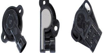
Flat-Response Knock Sensor

The two-wire, flat-response knock sensor requires either an attaching bolt or stud for attachment to the engine. The flat-response knock sensor was introduced with the 2005 LS2 engine and with the 2001 4.3L Vortec engine. With proper calibration changes and a little engine wiring work, the early LS-series PCM can be configured to use the flat-response knock sensors. It’s a convenience for LS2 engine swaps into LS1 vehicles.
You must be registered for see images attach


=-===========================

Interestingly enough.. this is not necessarily accurate. The black box GMT-400's use two knock sensors, one on each side(at least in the L29 454 version). The Gen III LS motors have two in the valley cover and the Gen IV ones have two not in the valley cover(they wouldn't have room with the AFM/DOD stuff in there), although there is some variability in that as well.
I got it from a website, which i recreated the entire knock sensor section above
if its still wrong, let me know. Since It wasnt all inclusive i didnt want to mislead if you at least saw some problems lol, so I found the rest
 

SirRobyn0

Full Access Member
Joined
Dec 6, 2019
Posts
6,742
Reaction score
11,316
Location
In the woods in Western Washington
First Name
Rob
Truck Year
1984
Truck Model
C20
Engine Size
305
Ok, so for anyone that hasn't been following my other thread and has been wondering why I haven't made a move or given an update on my ESC issues back in the end of February my #7 spark plug started fouling out. Like every 100 miles bad. Ultimately I did valve stem seals that did not help and a intake manifold gasket which turned out to be the problem. So the oil control issues are taken care of and now I'd like to get back on to fixing the ESC. Of course I cleared out the passages for the EGR in the intake manifold while it was off.

Where I left off the, knock sensor located in the right side of the engine block and extends into the coolant jacket in the block is fused in place. I broke the top of it off in order to get to the inter part of the sensor where a wrench can be put on the stem. That, heating it up as much as I can without destroying the oil pan gasket, and penetrating oil and it still won't come out.

The plan was to relocate the knock sensor to the drivers side of the engine block in the water jacket plug over there, which I plan to do this weekend, but first I will give getting the stem of the sensor out of the passenger side another shot. I don't wanna drill it, because there is coolant behind it obviously it will be messy. Only if the sensor is ineffective on the other side of the engine will I drill the original stem out.

Before I even do that I'd like to test the ESC module's ability to retard the ignition timing. Obviously I know it's functioning on some level or the truck would not run or run badly, but I assume when the knock sensor hears pinging it grounds out the single wire to it. So could I test that part of the system by starting the truck and grounding out the sensor wire while watching the timing marks with a light to see if it retards 4 degrees? @Turbo4whl any thoughts on testing the system like that? BTW my wiring looks good into the firewall. I'd image it might be worth while to remove the glove box to make sure everything looks ok back there as well.
 

SirRobyn0

Full Access Member
Joined
Dec 6, 2019
Posts
6,742
Reaction score
11,316
Location
In the woods in Western Washington
First Name
Rob
Truck Year
1984
Truck Model
C20
Engine Size
305
So my understanding is that the ESC is capable of backing down the timing a total of 8 degrees. 4 when ping starts 4 more if it continues, total 8. I also understand that the vacuum can on an ESC distributor is capable of advancing about 22 degrees (crank). So to that end, in the realization that my 305 is old and may have issues, I've ordered an adjustable vacuum canister for the distributor so I can limit that if need be.

Hoping that Sunday morning will be my work morning, but it might end up being Monday morning it just depends on how things go this weekend.
 

Turbo4whl

Supporting Member
Supporting Member
Joined
Oct 30, 2019
Posts
2,884
Reaction score
6,485
Location
Downingtown, PA
First Name
Wayne
Truck Year
1974
Truck Model
Jimmy
Engine Size
350
So @Ellie Niner knew the name I could not remember.

piezoelectric microphone

The test, in chassis, is to hit the exhaust manifold rapidly with a wrench. I would think if you threaded the sensor (mic) into anything, large, that was cast iron, you could test the system. Do you have a spare cast iron intake? Engine on, timing light hooked up, set the extra cast iron on the inner fender, make the test.

Maybe better, if you can, remove the threaded vacuum fitting on your engine's intake, mount the sensor there for a test??

........ but I assume when the knock sensor hears pinging it grounds out the single wire to it. So could I test that part of the system by starting the truck and grounding out the sensor wire while watching the timing marks with a light to see if it retards 4 degrees?
Grounding the sensor will not work. Very sensitive microphone listening for, basically one note and no other.

Edit: Listening for one note, repeatedly.
 
Last edited:

SirRobyn0

Full Access Member
Joined
Dec 6, 2019
Posts
6,742
Reaction score
11,316
Location
In the woods in Western Washington
First Name
Rob
Truck Year
1984
Truck Model
C20
Engine Size
305
So @Ellie Niner knew the name I could not remember.

piezoelectric microphone

The test, in chassis, is to hit the exhaust manifold rapidly with a wrench. I would think if you threaded the sensor (mic) into anything, large, that was cast iron, you could test the system. Do you have a spare cast iron intake? Engine on, timing light hooked up, set the extra cast iron on the inner fender, make the test.

Maybe better, if you can, remove the threaded vacuum fitting on your engine's intake, mount the sensor there for a test??


Grounding the sensor will not work. Very sensitive microphone listening for, basically one note and no other.

Edit: Listening for one note, repeatedly.
Thanks for that. So I had forgotten the name to "piezoelectric microphone", I recall one of you mentioning that to me at some point.

So I made the assumption that with one wire leading to the knock sensor, that the way it told the ESC module about the knock was by grounding the wire out as opposed to actually transmitting the sound to the module. Regardless I don't want to risk damaging the ESC module, so what I'll probably do is just go ahead and move the knock sensor to the drivers side, hook it up and test it.

If either you or @Ellie Niner could talk to me about the rest of the system a little bit that would be great. I understand the tip in senses sudden vacuum drops and gets hooked to manifold vacuum. I'm good there.

I know how the vacuum advance was setup from the factory, but I'm a little marginally concerned about my lack of any of the factory vacuum controls. The PO stripped the truck of the OE vacuum lines, and most of the check valves and temperature vacuum switches. Since the ESC system uses ported vacuum after it is warmed up, I could connect it to ported vacuum. I do not have a way (at least not easily) to set up the "trapped" manifold & ported vacuum system that was used when the engine is cold. So I'm temped for that reason just to connect it to manifold vacuum. As I'm sure you know manifold vacuum has certain drivability and often idle quality benefits. Since the ESC system does not monitor advance in anyway, it merely listens for knock and retards timing electronically though the module I don't think it will matter how I hook up the vacuum advance provided that it works in a way I'm happy with. What do you think?
 

AuroraGirl

Full Access Member
Joined
Sep 8, 2019
Posts
9,209
Reaction score
6,193
Location
Northern Wisconsin
First Name
Taylor
Truck Year
1978, 1980
Truck Model
K10, K25
Engine Size
400(?), 350
I like the phrase that helps understand what it does a lot, id say. But the cast iron question is a good one and it makes sense.
Thanks for that. So I had forgotten the name to "piezoelectric microphone", I recall one of you mentioning that to me at some point.

So I made the assumption that with one wire leading to the knock sensor, that the way it told the ESC module about the knock was by grounding the wire out as opposed to actually transmitting the sound to the module. Regardless I don't want to risk damaging the ESC module, so what I'll probably do is just go ahead and move the knock sensor to the drivers side, hook it up and test it.

If either you or @Ellie Niner could talk to me about the rest of the system a little bit that would be great. I understand the tip in senses sudden vacuum drops and gets hooked to manifold vacuum. I'm good there.

I know how the vacuum advance was setup from the factory, but I'm a little marginally concerned about my lack of any of the factory vacuum controls. The PO stripped the truck of the OE vacuum lines, and most of the check valves and temperature vacuum switches. Since the ESC system uses ported vacuum after it is warmed up, I could connect it to ported vacuum. I do not have a way (at least not easily) to set up the "trapped" manifold & ported vacuum system that was used when the engine is cold. So I'm temped for that reason just to connect it to manifold vacuum. As I'm sure you know manifold vacuum has certain drivability and often idle quality benefits. Since the ESC system does not monitor advance in anyway, it merely listens for knock and retards timing electronically though the module I don't think it will matter how I hook up the vacuum advance provided that it works in a way I'm happy with. What do you think?
It doesnt produce sound or ground ,piezoelectric is saying that the sensor creates a signal, its grounded into the engine block and then to the battery through that means, but the signal it creates is what is being Looked for
I assume when it meets a threshold but doesnt exceed another, it pulls timing 4 degrees if you are correct, then if it still sees more it will step in and pull 4. the control logic I would assume is in the ESC Module and that would be critical to be the right module for the engine and the right sensor for the module. Dont know if it was different car vs truck but the way i worded that was me insinuating if you could get that same engine in a car, then you probably had the same sensor maybe, and same module (IF they would use the same strategy. a car is potetnailly under less load, different timing)
 

AuroraGirl

Full Access Member
Joined
Sep 8, 2019
Posts
9,209
Reaction score
6,193
Location
Northern Wisconsin
First Name
Taylor
Truck Year
1978, 1980
Truck Model
K10, K25
Engine Size
400(?), 350
You must be registered for see images attach


xc_hide_links_from_guests_guests_error_hide_media
 

SirRobyn0

Full Access Member
Joined
Dec 6, 2019
Posts
6,742
Reaction score
11,316
Location
In the woods in Western Washington
First Name
Rob
Truck Year
1984
Truck Model
C20
Engine Size
305
@AuroraGirl thanks for that. Thanks for the Piezoelectric basics. Everything I've read says the ESC, when it detects knock will pull 4 degrees and if the knock continues will pull 4 more, 4+4=8 total. I have no idea how long it has to keep hearing the knock to pull the 2nd 4 degrees out.

I find it interesting to note that in the diagram you posted he's setup an ESC system running the standard 4 pin module, where as the actual ESC distributors run a 5 pin module or at least mine does.
 

Ellie Niner

Full Access Member
Joined
Aug 7, 2021
Posts
379
Reaction score
613
Location
Tucson, AZ
First Name
Tory
Truck Year
1986
Truck Model
K10 Silverado
Engine Size
LE9 305
@SirRobyn0 My brain is a little cooked right now from work, life, and the loss of a family pet, so I have a moderate case of Can't Remember Sh¡t, but I'm finally getting ready to dig into my ESC again, so should refresh my memory on the fuzzy details either this weekend or next.

The tip-in switch on mine will blip the timing back for less than a second if I pull a vacuum on the switch, then dump it quickly. I remember rapping on an exhaust manifold with a Crescent hammer some years ago (I've been meaning to fix this for years now), and RPM changed (didn't have a timing light on it, so not sure how much). It also retards the timing sometimes when I close the hood, but it also goes full retard at random... and sticks there for varying amounts of time... so I know the ESC computer is t¡ts. I thought I saw about 10 degrees of timing pulled, but it may have been 8.

I have light duty emissions, low altitude spec, and my vacuum advance is connected to manifold vacuum only, but runs through a delay valve that slows the bleed off of vacuum above or below a certain temperature (controlled by the same TVS that operates the EFE), then goes to straight manifold vacuum at the other temperature (can't remember which way is which). The delay valve clogged up a long time ago, causing the engine to detonate badly much of the time, so I did a temporary "fix" by hooking the vac advance up to venturi vacuum and adjusting the timing. It's never been quite right, so I'm going to be looking up an ESC computer, a correct delay valve, and I think I might need a new TVS too... the other TVS that handles EGR, purge, and TCC checked out a long time ago, so that's on the list, too.

If nothing else blows up in the meantime I'll get to work on this thing, post what I find out and tag you...
 

SirRobyn0

Full Access Member
Joined
Dec 6, 2019
Posts
6,742
Reaction score
11,316
Location
In the woods in Western Washington
First Name
Rob
Truck Year
1984
Truck Model
C20
Engine Size
305
@Ellie Niner I hear ya on work and life being so busy sometimes the brain is just fried. I get to close with our dogs and it is so hard on me when one of them passes.

Update on the ESC:
I decided that my first move would be to remove my glove box just to make sure the module is hooked up and looks ok and all that stuff. Guess what I found in there. Module is gone. The harness connector was cut off and the distributor wires are connected together so it would run. Much like guys do at the distributor as the ESC bypass, but someone has done it under the dash. The truck came from Oregon I have no idea if DEQ does a visual inspection. Maybe someone one was concerned about that. Well I guess it doesn't matter why at this point.

So I have to get some parts together now to even have a chance at getting the ESC working. I'm tired of not having any sort of vacuum advance so I'm going to install the adjustable one so I can have something for vac advance anyway in the mean time.

So no need to rush any info to me. I do still want to get the ESC working but will have to source a module and connector and go from there. Thanks.
 

SirRobyn0

Full Access Member
Joined
Dec 6, 2019
Posts
6,742
Reaction score
11,316
Location
In the woods in Western Washington
First Name
Rob
Truck Year
1984
Truck Model
C20
Engine Size
305
Ok, well here is my report for the day. I did, I guess you'd call it a distributor tune up today, but not a full rebuild. IDK, what thread it was in but I mentioned somewhere along the lines, that the mechanical advance was not the best, it was a bit sticky. I've had the distributor out enough times now to know the shaft is in good shape and so is the gear. It's got an new module, cap and rotor on it. All standard / blue streak parts. So today I went in there pulled the springs off the mechanical advance, carefully cleaned up the weights, and applied a little dielectric grease to the moving parts. Didn't have to much play in the pins, and didn't look like the weights had been dragging. Put the springs back on and it's working good. Then installed an adjustable vacuum advance unit. Set it to about 10 degree to start out with, and I'll either go up or down from there.

So my plan tomorrow is to take the truck out run a few high RPM passes with the vacuum advance disconnected and adjust the timing to just below where it pings. Then hook the vacuum advance up and set it so it doesn't ping in lower RPM ranges, but still gives me some advance. I'd kind of like to have the vacuum advance hooked to manifold vacuum, but with the 700R4 it likes to lug sometimes in overdrive for a few seconds before it shifts, so ported maybe better for that. We'll see either way this should be better than no vacuum advance at all, and with any luck I'll see a small fuel economy increase, but that should hold me until I find the needed parts for the ESC.
 

SirRobyn0

Full Access Member
Joined
Dec 6, 2019
Posts
6,742
Reaction score
11,316
Location
In the woods in Western Washington
First Name
Rob
Truck Year
1984
Truck Model
C20
Engine Size
305
Ok so here is my update for today. I followed though on my plan. I took the truck out and drove it for about an hour to get it good and warmed up. Then with the vacuum advance disconnected I started playing with the base timing in an effort to dial in the mechanical advance. I know some would say what I'm doing here isn't really right, and it's not that is true, but this is suppose to be a stop gap until I get the ESC functioning. So I played with the base timing and then took runs at this hill which I can do in 2nd gear and run it though the RPM range looking for the most advance I can run without having it ping. At 2 degrees BTC I get just the slightest ping when I tip over 3,000RPM. That's fine I locked down the distributor there and I'm happy with that.

For the vacuum advance I started with it set for 10 degrees of advance and hooked up to ported vacuum. I slowly ran the amount of advance up until it pinged. For me the most likely ping point is in over drive when slowing down a bit to about 40MPH the 700R4 likes to lug the engine a little bit so right there at 18 degrees of advance it'll ping pretty good so I dropped it down to 16 degrees. Drove it a bit and then changed the vacuum source to manifold, which of course required that I readjust the mixture screws and idle speed on the carb, but wow she sure likes manifold vacuum for the advance. And just adding 16 degrees of vacuum advance makes the idle so much smoother, the of idle power so much stronger and smoother. At cruse at higher speeds it'll hold over drive so much better because than bit of advance improves the power so I'm not on the throttle so much. Once I got into the city and sat in some traffic I did get some light pinging at high vacuum points, but for right now I'm just going to leave it. I can always take another couple degrees out of the vacuum advance if I need to. If I ran premium that ping would be gone, but we all know how expensive gas is right now. Also as I mentioned in the spark plug thread it's likely I'll step the heat range on the spark plugs down in the near future as ones I'm running right now are a step hotter than what use to be in there. So that also might help with the remaining ping.

Certainly what I have going on now 100 times better than when I tried that standard distributor! So that should hold me until I get the ESC parts together and allow me to move on to the next project for now.

Thanks for all the input guys, and helping me to better understand the ESC.
 

SirRobyn0

Full Access Member
Joined
Dec 6, 2019
Posts
6,742
Reaction score
11,316
Location
In the woods in Western Washington
First Name
Rob
Truck Year
1984
Truck Model
C20
Engine Size
305
Ok I'm sick of trying to manage the engine timing manually and running around with the timing retarded. So I'm back on to trying to get the ESC working again.

What I did today. Repaired the wiring harness under the dash and installed a used ESC computer. Then I crawled under the truck and installed the knock sensor. So if ya'll remember one of my early set backs was the original knock sensor was broke off close to the block. I could get vise grips on it, but even heating it up I couldn't get it out. So I extended the knock sensor wire. When I cut the wire to the sensor it looks just like regular wire, we talked about that pages ago and someone thought that it might be special wire to transmit sound. Mine is not, it's just regular wire. So I extended it about a foot so right now the wire runs under the oil pan and I'm installed the sensor in the coolant plug on the drivers side now.

You must be registered for see images attach


By the time I got done with that I was pretty much out of time, but still hooked up a timing light, fired it up, perched fat self on my knees on the top of the core support and watched the timing light while I tapped on the driver side exhaust manifold. I used a standard carpenters hammer. I did not see the timing change.

So this is a pretty darn simple system. If I drive the truck today I will get it under the conditions it likes to ping at and see what happens. A side from that I'm not really sure if I tapped hard enough, long enough or fast enough to trigger the knock sensor. From there I'll test for power getting to the ESC module, which I did not do, but I assume it would not run if there was no power to the module.

Ok I'm open to your thoughts as well. Other than this truck I have not done a lot work on a ESC system. It seems simple enough, but open to advise from those that know more than I on this system. Thanks.
 

Ricko1966

Full Access Member
Joined
Apr 11, 2017
Posts
4,065
Reaction score
5,909
Location
kansas
First Name
Rick
Truck Year
1975
Truck Model
c20
Engine Size
350
If it doesn't work out Robyn I think I have a solution. Leaving for Kansas city right now. I'll check in later.
 

Turbo4whl

Supporting Member
Supporting Member
Joined
Oct 30, 2019
Posts
2,884
Reaction score
6,485
Location
Downingtown, PA
First Name
Wayne
Truck Year
1974
Truck Model
Jimmy
Engine Size
350
As discussed before, my '82 has a shielded wire to the sensor. Most important is to have a good connection to the core wire as the sensor is actually a microphone generating current.

For the test I was shown hitting the exhaust manifold with a wrench. I have always used a 3/4" wrench that may have a different sound than the hammer.
 

Forum statistics

Threads
42,116
Posts
909,494
Members
33,611
Latest member
RNFL
Top