Geez
Normally I only do this for supporting members.
Class is in session. You in the back, STFU!
So it's for a 'Vette. It's GM and that's all you need to know. A Cruise Master is a Cruise Master.
Yes there are several different stalks and I ain't goin' there.
"Cruise Master" Cruise Control Diagnostics
I've read a lot of people's dilemmas about the cruise not working, or having a mind of its own, so here are the details of what I did to get mine going again. People complain about these things "hunting" around the set speed, or just pulling the throttle down so you rocket off to the horizon. Not a good prospect in a car that might have several hundred horsepower to be unleashed. If this is the case, then hopefully these pages will help to iron out any problems. I've struggled to find any good info about these things in any of the shop manuals, so I hope the following will be useful and interesting and fill a bit of a gap in the literature. So far, I have found only one place with good info on the cruise system. This is at the
1980 Vette registry. There are some excellent technical articles here about many aspects of the Vette. The cruise article explains the workings of the inside of the transducer very nicely, so it is not my intention to repeat too much of that, except for where it will help in knowing what's wrong with yours and how it’s put together. If you really want to get carried away, then I found what appears to be an original 1969 patent for this design, at the
US patent office site. Search for patent number 3441104. It's pretty heavy reading (!) but is quite useful once you get round the style of writing.
The following applies to any of the 77 to 80 Corvette transducers, without the resume function. The 81-82's have similar transducers but an additional "resume solenoid". The wiring and switching layout are necessarily a bit different for the later models. However, there are many similarities in the two systems, so hopefully this might be of some use to the later model people. Also, I guess there are many other GM vehicles that used these systems.
A quick explanation of how the system works would help here:
When you engage the cruise, a voltage is applied at the "engage" terminal on the transducer. This snaps a solenoid valve closed, which effectively connects manifold vacuum to the throttle servo (The rubber disc-shaped thing on a bracket on the top of the engine). After you've pressed the cruise button and released it, a small current through the resistance wire ("hold" terminal) holds the solenoid valve closed - the current needed to hold a solenoid open is less than what you need to actually trip it in the first place. There's a speed-controlled bleed valve inside the transducer that lets more or less atmospheric air into the vacuum pipes, depending on whether the throttles need to be opened more, or closed more, to maintain a constant speed. The atmospheric air comes into the system through a filter in the bottom of the transducer, then through the bleed valve. If you step on the brake, the small hold current is cut, and the solenoid valve pops open, disconnecting the throttle servo from its manifold vacuum supply. Also, a valve on the brake pedal opens, to let atmospheric air into the servo so it quickly relaxes and the throttles close.
Bear in mind that this system is a fairly simple (and dare I say it, fairly crude!) one - but that's part of what I found fascinating about it. After all, the original design could be nearly 40 years old now. A good cruise master system with no leaks, dirt etc. should hold speed reasonably well. But it's not a computerized device that measures throttle position, as a new cruise system would. OK, you can argue that it implies throttle position, since manifold vacuum, the driving force of the system, is quite linearly related to throttle position at a constant engine speed (hence road speed). I'm not going to dive into an in-depth discussion about the relationship between throttle position, road load and engine speed, partly because I'm sure there are many out there who would tell me I don't know anything, but mainly because I hope it won't be necessary... I hope the following should be more than enough to help you get your old cruise system up and going again.
If your cruise doesn't work, or it won't hold a speed, then before ripping out the transducer and replacing it, there are quite a few other checks to make. The vacuum and physical checks apply more to a system that either doesn't work at all, or that works but won't hold a speed. The electrical checks probably apply best to systems that just don't work at all...
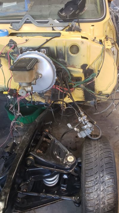
Pic 1 Here’s how it all looks in-situ.
You must be registered for see images attach
The “source” vacuum comes in at pipe B; this pipe should lead down to a tapping in the manifold.
Pipe A is the vacuum “outlet” from the transducer.
Pipe C is the bleed pipe. This is plugged onto the bleed orifice tube (brass fitting on the side of the transducer) and allows atmospheric air to come back into the system, via the filter in the bottom of the transducer.
Pipe D goes off to the servo to hold the throttle open.
Pipe E is the brake pedal vacuum release pipe When you hit the brake, not only is the electric circuit broken, but a valve on the brake pedal switch opens, immediately equalizing the vacuum pressure and letting the servo relax to close the throttles.
F is the earth lead for the system. This goes down to a chassis earthing point near the evap canister, by one of the driver side body mounts.
G is the engage wire
H is the hold wire.
Adjusting the set-speed
If your only problem is that, when you set the cruise, it settles at a speed slightly higher or lower than where you set it, then you can quite easily adjust for this. Screwing the orifice tube in or out is the method here. Take out the washer bottle filler neck. Loosen the locknut on the brass bleed tube (where pipe C plugs on). It's probably easier to leave the pipe attached if you're careful. Screw the tube in or out about 1/4 turn for each mph error - if your cruise creeps up after setting, screw the orifice tube inwards. If it loses speed after setting, screw the tube out. Then tighten the lock nut up again. Don't go mad, as it's only made of brass! Also - don't pull the tube right out of the transducer unless you're planning to open the thing up. You won't be able to get it back in otherwise!
Troubleshooting
Pics 2(See next page)
You must be registered for see images attach
You must be registered for see images attach
Above are some pages from the shop manual that show the circuit diagram and component location. Note the wire colors are different at the transducer plug - they're the right color, but swapped round! Don't know if it's my car or the manual that's wrong.
Physical Checks
The obvious one is to check your speedo cable from the transmission – although if that’s broken or disconnected, it should be fairly clear, since the speedo won’t work!
Another check that is more to do with maintenance than repair is to adjust the servo linkage. On the carb, make sure the choke cam is rotated back so that the throttle can close completely. In this position, the linkage from the servo should have no slack in it at all. Mine has a rod for the linkage – you unclip it from the throttle and screw it in or out to lengthen or shorten. I think some are made from chain, in which case you take out links to shorten it. Adjust it if necessary, so that it lets the throttle go right back to closed but has no slack when it's there.
Pic 3 Servo and throttle linkage.
You must be registered for see images attach
Vacuum checks (refer to picture 1)
Check for condition and connection of all the vacuum hoses. They should be free from cracks and badly collapsed spots, or any blockages. A length of tube used as a makeshift stethoscope is useful for probing around to listen out for any hissing leaks. Pull them all off if necessary and use the photo as an aid for reassembly. A vacuum pump is a really useful investment for this task, as it gives quantifiable results. Just sucking on the end of the pipes is all very well, but unless you have calibrated lungs, it's tricky to know if you have a slow vacuum leak. To really isolate a slow leak, you will need a pump.
Take off pipe B and being careful not to let it suck any crap up, check that there’s vacuum from it with the engine running. Stick your finger over the end of it and see if it holds a vacuum. If you have a vacuum gauge, then it should register at around the vacuum level for the inlet manifold at idle. This is engine dependent (lumpiness of cam etc.) but I suppose about 15 - 20 inches of mercury ["Hg] (that's about 7.5 - 10 psi) would be about right.
With the engine off, pull off pipe D and pull a vacuum on it with a vacuum pump. Depending on how good your lungs are, you might be able to do this without a pump! This should pull the servo back and hold the throttle open. Make sure it stays holding and doesn’t leak. Pull about 14 "Hg on it - this will be more than enough to pull it flat. The servo and its pipe should not leak down more than about 5" in 1 minute. Notice how little suction you actually need to move the servo over its range - given that the engine can pull 15 to 20 inches or more at the manifold, which shows just how much vacuum must be "vented" out of the bleed orifice inside the transducer!
Remove pipe E and pull a vacuum of about 15 inches in it. It should not lose more than 5 inches in 20 seconds. Then step on the brake. The vacuum should release. If the brake switch is leaking, or not working OK, then it’s time for a trip under the dash!
Electrical Checks (picture 1 again)
The system runs through the gauges fuse on the 1980 – so check that’s not blown first (not that it won’t be obvious if your gauges don’t work!) Not sure if it’s the same fuse for other years, so check your manual.
Make sure all the connectors are clean.
First check the continuity of the earth wire F. Undo the nut and bolt, then using an ohmmeter you should get a reading of zero or very nearly zero ohms to ground. If not, get under the car and check where the wire bolts to the chassis.
Switch the ignition to run and make the following checks as you move the cruise switch in the indicator stalk. The cruise switch has three positions, depending on how far you push it in.
1. Release or cruise
2. Engage
3. Trim
Disconnect the plug from the top of the transducer and check for voltages with a multi-meter.
The engage wire (G, blue) should read zero volts with the cruise button released. Pushing the button in just slightly, to the second position, should give you 12 volts at the engage wire. Pushing the button right down to the trim position should give you zero volts again.
The hold wire (H, green) should give 12 volts with the cruise switch released, 12 volts with the switch in the second position, and zero down at the trim position.
The table summarizes what you should see:
| Cruise Switch Position | Voltage | | |
| Engage Wire (H) | 1 – cruise | 0 | |
| 2 – engage | 12 | | |
| 3 – trim | 0 | | |
| Hold Wire (G) | 1 – cruise | 12 | |
| 2 – engage | 12 | | |
| 3 – trim | 0 | | |
| | | |
If there’s no juice at these wires, then follow them back as far as possible to check for breaks, and check that the brake release switch isn’t stuck open. This will unfortunately mean going under the steering column.
To see the brake release switch working, put the cruise switch into any of its positions where a voltage is expected from either of the wires. Push the brake pedal and the voltage should go to zero in all cases.
Finally, you can check the continuity of the solenoid inside the transducer. You can do this in-situ, although I’ve shown later how to do it when it’s all apart. Take off the hold/engage plug and check the resistance between the hold terminal and a clean bit of the body (i.e., where the solenoid is grounded). This should be around 5 to 7 ohms. If it’s infinite, then it suggests the solenoid has a broken winding or a bad internal earth. This will stop the cruise engaging, even if everything else works fine. Time to go inside the transducer.
If everything checks out here, and you still have problems, it's decision time. Pull the transducer apart or just put a "new" one in?
Provided all the parts are serviceable and if you're careful, there's no reason not to at least have a go at cleaning up an old transducer.
The transducer rebuild tech will cost you extra.