gas gauge dual tank

Disclaimer: Links on this page pointing to Amazon, eBay and other sites may include affiliate code. If you click them and make a purchase, we may earn a small commission.

deanobigred

Junior Member
Joined
Jan 5, 2017
Posts
19
Reaction score
0
Location
omaha, Ne.
First Name
dean
Truck Year
85
Truck Model
k1500
Engine Size
350
I have a 85 k1500 and I have gone through and fixed all other gauges but I'm not where to start with my gas gauge I have movement (not starting from e) but does anyone know if there is a step by step and where I can get a shop manual. and by the way is it me or is there something wrong with the search here ?
 

84 C20

Full Access Member
Joined
Sep 24, 2014
Posts
80
Reaction score
102
Location
Dallas, Plaestine, Gun Barrel
First Name
scuddy
Truck Year
1984
Truck Model
C20
Engine Size
350 sb
From my experience with a slightly moving fuel gauge:

Clean the connections to the fuel sender and ground
Clean out the connections at the tank selector valve
Check for any grounding of the wire that goes up to the console
Bench test the fuel gauge to make sure it works
Check the printed circuit board the gauges connect to (if the 85's had those)


I had a problem where the signal wire was broken somewhere but the casing was perfect. Had a miserable time trying to figure out why it wasn't showing fuel level when everything I checked indicated it should be working. I ended up splicing a new wire in and it worked like advertised.
 

deanobigred

Junior Member
Joined
Jan 5, 2017
Posts
19
Reaction score
0
Location
omaha, Ne.
First Name
dean
Truck Year
85
Truck Model
k1500
Engine Size
350
Bench test the fuel gauge to make sure it works

so how do I do that ?
 

chengny

Full Access Member
Joined
Feb 22, 2012
Posts
4,086
Reaction score
1,008
Location
NH
First Name
Jerry
Truck Year
1986
Truck Model
K3500
Engine Size
350/5.7
I have a 85 k1500 and I have gone through and fixed all other gauges but I'm not where to start with my gas gauge I have movement (not starting from e) but does anyone know if there is a step by step and where I can get a shop manual. and by the way is it me or is there something wrong with the search here ?

The tank level indicating circuits in a dual tank installation can get involved. Better to do it as below.

First thing is I am assuming that both tank levels are not indicating correctly.

If that is in fact the case, do this diagnostic:

Locate the extension that is spliced (onto the common pink wire) and just pop the two leads apart. When you have the section of wire - that comes from the gas gauge on the dash cluster - disconnected, ground it to a good clean area on the frame. Then turn the ignition switch to RUN and observe the gauge. With no resistance to ground in the sensing leg (the PNK -30 lead), the gauge should be pegged low.

A further test would be to isolate the PNK-30 lead - coming from the gauge - from any possible ground (just let it hang in the air). Now, if the gauge and all the wiring up to the extension splice point are in good order, the gauge should peg high.

As a corollary, if the gauge reacts as described above during the tests, but does not function when the splice is re-connected...there is a problem in the extension side of the PINK-30 (or in the tank selector valve control head). On the other hand, if the gauge does not respond as described to the tests, we have to look at the condition of the PINK-30, the power supply to the gauge and the gauge itself.

If necessary, we can check those other things. But it is always best to do the easiest things first - I think so anyway. I am one lazy SOB!

Here are some images to help explain - I am not so articulate tonight:

You must be registered for see images attach


That extension was simply a cheap way to allow the sensing leg to be run over to the Pollak valve. It normally would have been to run only to the sender on the single production tank.

BTW - I am color deficient almost to the point of being color blind, so don't go by the colors I use to trace wiring diagrams. I tried for pink but it looks kind of gray.
 
Last edited:

chengny

Full Access Member
Joined
Feb 22, 2012
Posts
4,086
Reaction score
1,008
Location
NH
First Name
Jerry
Truck Year
1986
Truck Model
K3500
Engine Size
350/5.7
Just as a general discussion on the gauge/sender/chassis relationship - and to make sure I have the theory of operation straight in my mind;

The components mentioned above - when connected by the pink (hot) and blue (ground) wires - form the "sensing leg" of the gas gauge located in the instrument panel.


12 volts is supplied to the positive terminal of the sender (via the pink wire). It's source is the negative side of the gauge's measuring coil.

The less resistance in this total combined circuit, the greater the electron flow through the coil wires - and consequently the stronger the force is that it (the measuring coil) can exert on the gauge's magnet. The magnet is attached to the lower end of the indicating needle.

In addition to the sensing leg, there is another - opposing - circuit called the "control leg". It is identical to the sensing leg in every way except that the negative side of it's coil is lead straight to ground (rather than through a variable resistance and then to ground like the sensing leg). Also, it's coil is located on the opposite side of the magnet from the measuring coil's.

So what you have is; two coils located on either side of an indicating needle - AKA the "ray". The ray is pivoted somewhere in the middle and has an integral magnet mounted at the bottom.

These coils create their own magnetic fields - the strength of which is a function of the electron flow (i.e. current) passing through them. When these circuits are energized - by turning the ignition switch to the RUN position - the opposing magnetic fields begin to "fight it out". Each coil tries to pull the magnet - mounted on the needle - towards itself.

Due to the fact that it's negative leg is run straight to ground - resulting in nearly zero resistance, the current flow through the control coil is essentially constant (as is it's magnetic force).

On the other hand, due to the variable resistance generated by the sender (as a result of changes in the fuel tank level), the current flow/magnetic strength of the measuring coil can be higher or lower than that of the control coil.

The location of the two coils - to the magnet - is such that:

1. The control leg is always trying to peg the indicating ray to the FULL end.

2. The sensing leg is always trying to peg the ray to the EMPTY end.

So as extreme examples:

1. If the pink wire to the sender is broken/disconnected the control leg exerts the greater force and pegs the needle Full.

2. If the pink wire is allowed to contact ground (before passing through the sender), the sensing leg has a greater force and the ray pegs low.


As GM explains it (better and way more succinctly than I can):

VARIABLE VOLTAGE TYPE
The variable voltage type dash gauge consists of two magnetic coils to which battery voltage is applied. The coils act on the gauge pointer and pull in opposite directions. One coil is grounded directly to the chassis, while the other coil is grounded through a variable resistor within the sending unit. Resistance through the sending unit determines current flow through its coil, and therefore pointer position.

When resistance is high in the sending unit, less current is allowed to flow through its coil, causing the gauge pointer to move toward the directly grounded coil.

When resistance in the sending unit decreases, more current is allowed to pass through its coil, increasing the magnetic field. The gauge pointer is then attracted toward the coil which is grounded through the sending unit.
 

deanobigred

Junior Member
Joined
Jan 5, 2017
Posts
19
Reaction score
0
Location
omaha, Ne.
First Name
dean
Truck Year
85
Truck Model
k1500
Engine Size
350
so I found that's its pegged full, but I have not found a broken pink wire, found that when I ground the pink extension at the plug it goes towards empty but when it all plugged correct it goes all the way to the right is it possible one of the coils are bad ? on the gauge. oh and thanks for the help.
 

chengny

Full Access Member
Joined
Feb 22, 2012
Posts
4,086
Reaction score
1,008
Location
NH
First Name
Jerry
Truck Year
1986
Truck Model
K3500
Engine Size
350/5.7
so I found that's its pegged full, but I have not found a broken pink wire, found that when I ground the pink extension at the plug it goes towards empty but when it all plugged correct it goes all the way to the right is it possible one of the coils are bad ? on the gauge. oh and thanks for the help.

No problem with helping, Deano but I am having some trouble following the results of the diagnostic -sorry, we'll get it.

1. Initially you posted this:
"but I'm not where to start with my gas gauge I have movement (not
starting from e)".
I understood that to mean: the gauge wouldn't move off
the empty end of the scale. Not correct, I guess - because now I see this:

2. so I found that's its pegged full, Do you mean that it is always
pegged full - like stuck? Or do you mean only when the ignition switch is
moved to RUN, then does the needle swing over to F?

3. but I have not found a broken pink wire,
It is not always easy to locate a damaged lead in that rear lighting/fuel
tank control harness. Very often the damage is internal (under the
insulation)and cannot be identified by visual inspection. That why we've
started figuring this out using the methods described. If you rather, we
can switch to using a Fluke meter -I just wasn't sure if you had one.
But if I am reading things right, that's (a broken PNK-30 lead) not the
problem anyway. If the gauge moves decisively toward the lower end of
the scale when the splice end of forward section of the PINK-30 circuit is
disco'd & grounded...that would indicate the conductors are intact. I think we can forget that - for now anyway.

4. found that when I ground the pink extension at the plug it goes towards
empty but when it all plugged correct it goes all the way to the right is it
possible one of the coils are bad ?


The test procedure was this: disconnect the two sections of PNK-30 at the
splice and ground the back end of the long wire - the one that runs from
the dash gauge. I apologize if I didn't explain it well, it really should have
only taken 5-10 minutes


It was not to ground the short extension that runs across the
crossmember to the tank selector valve.

What we were trying to determine was whether the components in the front
section of the circuit were operating properly (i.e. power to the gauge, a
functional gauge & and continuity in the long pink wire that connects to the
extension). If they were, we'd be almost done.

2. I'm completely lost on this one - I just don't get what you are trying to
say:

but when it all plugged correct it goes all the way to the right

I'll take a stab at it though. I think you are saying that: the power to the gauge, the gauge itself and the PNK-30 circuit all seemed to behave as designed during the tests, but when everything was placed back in actual operation...the gauge was indicating (incorrectly I hope) that the tank was full.

It brings me to what - I asked last night:

The gas gauge will not give an accurate reading on either tank - is that correct?

Also, please tell me that you know for a fact - at least approximately how much gas is in each tank.

Couple more:
How long you have had this truck?
Did the gas gauge ever work right?
Have you recently done any modifications or repairs behind the cab - particularly to the exhaust system or frame? If so what was done?
Is this problem only about tank level readings - or is the Pollak valve unable to switch from tank to tank also.

Here is the next step:

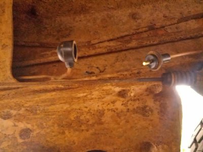
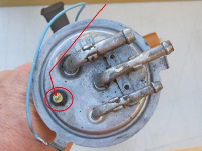
The PNK-30 circuit is completely independent of the tank transfer valve when the splice is disconnected. The gas gauge will read the level in whichever tank's sender the little brass button is pushed onto.

The LH tank is referred to as the production tank. The RH one is the auxiliary tank. Break the splice again and this time just pull the sensing lead off the production tank (only because it is right there by the splice) - that lead should be pink with a white tracer. The other one (blue or black) is the ground wire out off the sender to the frame. Check that there is continuity from the sender end of the ground wire to the frame, if there is - good. Then push the ass end of the long PNK-30 lead directly onto the little brass pin on the sender of the production tank. Sound the tank to get a basic idea of the level in it and fire the circuit up.

Get back to us with the results and we'll put fork in this ******.

You must be registered for see images attach


You must be registered for see images attach
 
Last edited:

deanobigred

Junior Member
Joined
Jan 5, 2017
Posts
19
Reaction score
0
Location
omaha, Ne.
First Name
dean
Truck Year
85
Truck Model
k1500
Engine Size
350
so let me try to make sense of my gibberish, starting from your #1

1, I found that my gauge was always moving towards full with the key turned to the on position no matter which tank I put it on the problem started with the needle at times on the off pos, it was facing dead south and would move clockwise, so when I ground the pink wire it went further counter clockwise so this made me believe that someone gad taken the needle off and reapplied it wrong, so I reapplied it so when I ground the pink wire it is a little below E and when I reconnect the pink wire and turn the ignition to on it goes a bit past full. that should take care of 1 and 2 and most of 3.
on my harness to the cluster gauge I have 2 pink wires that go to the gas gauge one goes to the other side of the harness and dead ends the other goes to the back of the fuse block or the fire wall plug not sure about that yet.
4 I am not sure what you are referring to when you say disconnect the two pink-30 (at the splice) I have not seen a splice and the diagram you copied would not load, just a cam girl, lol , also extension not sure on that either.
I gotta go back to work, I will finish this post in a bit
 

deanobigred

Junior Member
Joined
Jan 5, 2017
Posts
19
Reaction score
0
Location
omaha, Ne.
First Name
dean
Truck Year
85
Truck Model
k1500
Engine Size
350
ok I grounded the pink wire on the to the frame (the other day) pink wire from cab not at fuel sender, I think that's what you were saying.
so tanks, the tanks sound empty to me but I put 6 gallons in the driver side and no change in gauge from switching left to right on the selector.
what would make the gauge go all the way clockwise if not a full tank ?

so some answers you wanted I have only had the truck a few months
no the gas gauge did not work nor any other gauge for that matter (just gas gauge left tho)
I have not done any mods but the previous owner did and if I cant locate the problem I am going to have to remove the bed .
I was told this was a frame up restoration that was not finished (new frame) its just everything was done half assed and everything that I have gone through I have found that he lied through his teeth, that being said I have always wanted to have a square body to wok on , I GOT MY WISH, did I miss anything , o I can hear the tanks switching , pollak valve ?
 

chengny

Full Access Member
Joined
Feb 22, 2012
Posts
4,086
Reaction score
1,008
Location
NH
First Name
Jerry
Truck Year
1986
Truck Model
K3500
Engine Size
350/5.7
on my harness to the cluster gauge I have 2 pink wires that go to the gas gauge one goes to the other side of the harness and dead ends the other goes to the back of the fuse block or the fire wall plug not sure about that yet.

All harnesses have one pink lead coming in from the firewall. There is a splice at back of the instrument panel plug with two branch leads that feed two different pins. Only one is used. Which one of those pins - that gets used - depends on whether the cluster is equipped with a tachometer or not. Assuming you have no tach, the pin that is connected to the gas gauge (via the conductor in the circuit board) will be in the upper left corner. See the image. Yellow is non-tach and blue is the pin for tach applications:

You must be registered for see images attach


4 I am not sure what you are referring to when you say disconnect the two pink-30 (at the splice) I have not seen a splice and the diagram you copied would not load, just a cam girl, lol , also extension not sure on that either.

There is a pin & socket splice under the LH side of the cab - way at the back. Image is attached.

The button looking thing on the left is the end of the lead that comes from the dash - it is a female single pin socket. The pin on the right is the start of the extension that leads over to the Pollak valve.

Pull those wires apart and attach the lead coming from the dash (with the socket) directly to the pin on the production tank sender. Image also attached.

The production tank sender will then be wired directly to the gas gauge and all the tank switching circuits will be by-passed. See what happens with it wired like that.


I don't know why the images I posted to help you are not viewable. Maybe you can see the two I attached here. Unfortunately most of my images are too big to attach and must be shown as links. This is the first I have heard of them being non-viewable.

If anyone else is monitoring this thread, could you comment on this issue with the images?
 

Attachments

  • IMG_20131231_123520.jpg
    IMG_20131231_123520.jpg
    80.3 KB · Views: 190
  • IMG_0009.jpg
    IMG_0009.jpg
    73.6 KB · Views: 452

gmachinz

Harnessworx Inc
Joined
Nov 10, 2012
Posts
762
Reaction score
287
Location
Iowa
First Name
Jabin
Truck Year
1986
Truck Model
K10
Engine Size
350
You guys are all overlooking the most problem prone aspect of the fuel level circuit and it is the sender assembly itself. The variable resistor mentioned earlier is the resistor strip which the float arm travels along-as the fuel level changes, the arm contacts slide up/down the strip...., thereby changing the resistance to the gauge. As time (or, more accurately as mileage goes up) the contact strip wears the resistance away AND the contact arm becomes worn to the point where it may or may not make contact anymore-causing a fuel gauge to "suddenly" register after putting in a half tank or more of gas.

Given most people operate vehicles with fuel level between empty and half full, resistance strips are typically in good condition from half to full. The OEM GM senders are 0-90 ohm resistance so an easy way to check the sender outside of the tank is to probe the sender stud and the sender body with a multi-meter set to OHMS and slowly move the sender arm up/down against the resistor strip. For example my used sending units didn't read accurately because there was not good contact against the resistance strip-I slightly bent the arm in to create a better contact and voila-I got 3-96 ohms afterwards.
 

deanobigred

Junior Member
Joined
Jan 5, 2017
Posts
19
Reaction score
0
Location
omaha, Ne.
First Name
dean
Truck Year
85
Truck Model
k1500
Engine Size
350
thanks for the help chengy and gmachinz , I have movement that could be correct or atleast close, that button plug was bad I put male female connecters on and like I said I have move looking like it might e close (gauge changes when I change the selector switch) so I'm moving on. see me on dieseling carb and thermostat comes on but when its too hot, thanks again all comments and help is looked into.
 

chengny

Full Access Member
Joined
Feb 22, 2012
Posts
4,086
Reaction score
1,008
Location
NH
First Name
Jerry
Truck Year
1986
Truck Model
K3500
Engine Size
350/5.7
thanks for the help chengy and gmachinz , I have movement that could be correct or atleast close, that button plug was bad I put male female connecters on and like I said I have move looking like it might e close (gauge changes when I change the selector switch) so I'm moving on. see me on dieseling carb and thermostat comes on but when its too hot, thanks again all comments and help is looked into.

Dean, when you finally get a chance to come back to the gauges, try to re-index the indicator needle on it's axle (those are the correct terms, but pointer/ray & shaft are good) so that it provides you with an accurate tank level indication.

If the connector at the splice was ultimately found to be broken, then the following would indicate that the gauge was functioning as designed:

I found that my gauge was always moving towards full with the key turned to the on position no matter which tank I put it on the problem started with the needle at times on the off pos, it was facing dead south and would move clockwise, so when I ground the pink wire it went further counter clockwise

As noted above, increased resistance will drive the needle towards the "F" mark. The highest resistance value that will keep the needle in the readable range of the gauge is 88 ohms. With a resistance of 88 ohms in the gauge's sensing leg, the needle will be right at the "F" mark. As Jabin notes above, the greatest resistance that a GM fuel level sender can provide is 90 ohms.

So you can see that if the tank is topped off (and the sender's rheostat is offering the full 90 ohms) to the sensing leg, the needle will come to rest just a bit above the "F" mark.

Bear with me, I getting there.

In your case, if the connection was broken (or even just really loose) at the splice, the resistance at that point was probably huge - actually infinite, if the pin/socket were not touching.

It follows that - with resistance that high - the current flow through the coil in the gauge that drives the needle toward "E" would be minimal. The other coil - the one that wants to send it to "F" would kick the "E" coil's ass. The needle would then be driven down to the 6 o'clock position and stay there.

The gas gauge is the only one of the dash indicators that doesn't have a default position that it returns to when de-energized. It will stay wherever it was when the power was secured. Here are some images of me moving the gas gauge needle to different spots and showing that it stays there:

You must be registered for see images attach


The voltmeter pushed to 13 V and at it's de-energized position:

You must be registered for see images attach


If the coolant temp and oil pressure rays are moved, they will will slowly gravitate to about the middle of the gauge:

You must be registered for see images attach


You must be registered for see images attach


Now comes my point - thank frickin' God, Jerry:

Because you moved the gas gauge needle from its original position on the shaft/axle, the gauge is now probably mis-calibrated to a significant degree. With the circuit is now working correctly - when it is powered up, the axle is going to rotate the correct number of degrees as driven by the gauge's coils. It wasn't moved or adjusted, and is oblivious to the fact that the attached needle is now pointing to a way different spot on the arc than it wants to indicate.

Now is a great opportunity to customize your gas gauge. These gauges are notorious for reading well above "F" for a wicked long time. Then when they finally do start to fall, they drop like a rock, especially after they hit the 1/2 tank mark. You can't do much about that, but you can set the needle so that even when it shows empty, you will still have a gas reserve. How much is up to you.

Drive around until you run out of gas - like bone dry - then switch to the other tank. Go to the gas station and pump in however many gallons you want for a reserve and at that point - before filling up the rest of the tank - set the needle on the axle so that it shows "E". Don't put in too much or you'll show a full tank for days and then drop like a rock to "E" even faster than with the factory calibration. There is about 3 gallons capacity in the raised tank top at the rear of the tank that the sender never sees - you could use that amount as the reserve quantity.
 

75gmck25

Full Access Member
Joined
Oct 13, 2016
Posts
2,038
Reaction score
1,833
Location
Northern Virginia
First Name
Bruce
Truck Year
1975
Truck Model
K25 Camper Special TH350 NP203
Engine Size
5.7
I don't see any calibration marks on the gauge face, but on my older Fords they had two tick marks for calibration.

(on the Ford) You put a specific size resistor between the sending unit wire and ground, and then line the needle up with the tick marks. If you can't get it close to the tick marks using a fixed resistance, the gauge has to be replaced.


Bruce
 

chengny

Full Access Member
Joined
Feb 22, 2012
Posts
4,086
Reaction score
1,008
Location
NH
First Name
Jerry
Truck Year
1986
Truck Model
K3500
Engine Size
350/5.7
I don't see any calibration marks on the gauge face, but on my older Fords they had two tick marks for calibration.

(on the Ford) You put a specific size resistor between the sending unit wire and ground, and then line the needle up with the tick marks. If you can't get it close to the tick marks using a fixed resistance, the gauge has to be replaced.


Bruce

Yeah, agreed - if he hadn't removed and repositioned the needle on the pin - with infinite resistance in the sensing leg.

So, as it stands now, the pin and needle are no longer properly indexed with respect to each other. The pin is probably rotating to the correct spot, but the needle is pointing elsewhere.

I suppose he could go to Radioshack, buy a 90 ohm resistor, insert it into the sensing leg (in place of the tank sender), ground it to the frame, pull/reset the needle to the full mark and then reconnect the sender wiring.
 

Forum statistics

Threads
42,116
Posts
909,478
Members
33,611
Latest member
RNFL
Top